
Section
24 Hybrid electrical power systems
24.1 Scope
24.1.1 The requirements of this Section are applicable to ships having a main source of
electrical power which is provided by hybrid electrical power generation and
distribution systems within which the main electrical power demand is supplied by
two or more different types of power source or by stored electrical energy.
24.1.2 These requirements apply to the design, construction and integration of hybrid
electrical power systems, their sub-systems, machinery and equipment.
24.1.3 These requirements apply to hybrid electrical power systems which provide the main
source of electrical power and exceptionally, where permitted by the National
Administration, the emergency source of electrical power.
24.1.4 In addition to these requirements National Administrations may impose further
requirements. Where such requirements conflict with these requirements, the
requirements of the National Administration will take precedence.
24.2 Characters of classification and class notations (machinery special features)
24.2.1 Ships complying with the mandatory requirements of this Section will be assigned the
Hybrid Power machinery special features notation.
24.2.2 Ships complying with both the mandatory requirements and the additional optional
requirements of this Section will be assigned the Hybrid Power (+) machinery
special features notation.
24.2.3 Hybrid Power: Assigned to ships with an electrical power system
including a combination of two or more different types of power source or utilising
stored electrical energy to satisfy the ship’s main power demand. The system and its
component parts are in accordance with the existing applicable requirements of the
Rules and the requirements of Pt 6, Ch 2, 24 Hybrid electrical power systems.
24.2.4 Hybrid Power (+): Assigned to ships meeting the requirements for
Hybrid Power and the additional optional requirements for Hybrid Power
(+) specified within Pt 6, Ch 2, 24 Hybrid electrical power systems. The
additional optional requirements aim to provide for enhanced performance of the
electrical power system achieved through the consideration of system simulation,
system integration and dependability of the electrical power system during normal or
reasonably foreseeable abnormal operation.
24.3 Definitions
24.3.1 Hybrid electrical power system: A ship’s electrical power system
comprising sources, stores, consumers and distribution of electrical power together
with their associated controls within which electrical power is provided by two or
more different types of power source or utilising stored electrical energy to
satisfy the ship’s main power demand. This definition is independent of:
- the type of distribution system (see
Pt 6, Ch 2, 24.3 Definitions 24.3.8);
- the types and ratings of source, their physical location
and time duration of connection to the ship’s power system;
- the types of store;
- the types of connected consumer; and
- the presence or otherwise of electric propulsion.
24.3.2 Reasonably foreseeable abnormal condition: A reasonably foreseeable abnormal
condition is an operation, event, incident or failure that:
- has happened and could happen again;
- has not happened but is considered possible. Where the
likelihood is considered extremely unlikely or the consequences are trivial, and
no further prevention or mitigation action is to be taken, then this is to be
justified; and
- is planned for (e.g. emergency actions cover such a
situation, maintenance is undertaken to prevent it).
They should be identified by:
- using analysis processes that are capable of revealing
abnormal conditions;
- employing a mix of personnel including designers, Operators,
persons who carry out maintenance and competent safety/risk professionals with
relevant domain knowledge and understanding to apply the processes;
- referencing relevant events and historic data; and
- documenting the results of the analysis.
24.3.3 Source of electrical power: A source of electrical power produces
electrical power from an energy source such that its output may be connected to
ship’s electrical power distribution system (see
Figure 2.24.1 Source of electrical power). It
includes:
- Dedicated conversion where conversion is the changing of an
output with respect to its input and may include change of form (e.g. a.c. to
d.c. or d.c. to a.c.), change in magnitude (e.g. of voltage, current or
frequency), change in phase or change in reference (e.g. through galvanic
isolation);
- Management systems perform monitoring, control, protection
and safety functions that are likely to be connected to higher level ship wide
supervisory systems: and
- Systems providing control, alarm, monitoring and safety
functions such as control panel, governor, automatic voltage regulator (AVR) and
emergency shutdown (ESD) system for a reciprocating engine or gas turbine
generator.
This definition of source of electrical power is independent of:
- the type of source (e.g. rotating generator, waste heat
recovery system, wind generator, solar panel, fuel cell, photovoltaic
array);
- the type of distribution system (see
Pt 6, Ch 2, 24.3 Definitions 24.3.8); and
- the application of the source (e.g.
main/additional/emergency/transitional source of power).
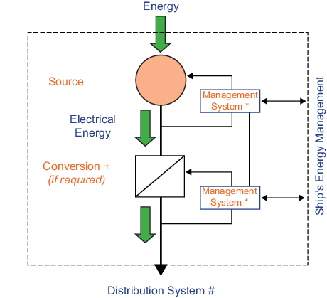
Figure 2.24.1 Source of electrical power
24.3.4 Additional source of electrical power: An additional source of power is a source of
electrical power not forming part of the ship’s main source of power that is rated
to supply a proportion of the ship’s main power demand at any time either
continuously or for an accepted period of time, e.g. an energy storage device or a
power take-off that is not rated for or capable of permanent operation.
24.3.5 Store of electrical energy: A store of electrical energy receives,
stores and discharges energy through a single point of common coupling with the
distribution system (see in Figure 2.24.2 Store of electrical
energy). It includes management systems and any required dedicated
conversion as defined in Pt 6, Ch 2, 24.3 Definitions 24.3.3.This
definition is independent of:
- the method of energy storage;
- the type of store (e.g. battery, capacitor);
- the type of distribution system (see Pt 6, Ch 2, 24.3 Definitions 24.3.8);
and
- the application of the store (e.g. power source, load
smoothing, peak shaving, dynamic response, power backup).
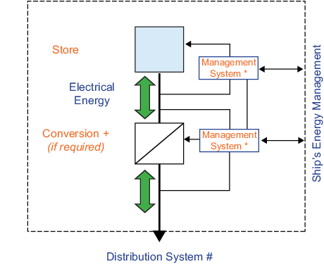
Figure 2.24.2 Store of electrical
energy
24.3.6 Consumer of electrical power: A consumer of electrical power takes its
input from the distribution system and delivers useful work through its associated
load ( see
Figure 2.24.3 Consumer of electrical
power). It includes management systems and any required dedicated
conversion as defined in Pt 6, Ch 2, 24.3 Definitions 24.3.3. Consumers
are present in any electrical power system and are not unique to hybrid electrical
power systems. The definition is provided here for completeness. This definition is
independent of:
- the type of load or the purpose for which it is
installed; and
- the type or physical form of distribution system.
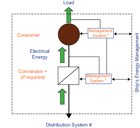
Figure 2.24.3 Consumer of electrical
power
24.3.8 Distribution system: The distribution system provides the interconnection between,
protection of and isolation of:
- sources (see
Pt 6, Ch 2, 24.3 Definitions 24.3.3 to Pt 6, Ch 2, 24.3 Definitions 24.3.4),
- stores (see
Pt 6, Ch 2, 24.3 Definitions 24.3.5),
- consumers (see
Pt 6, Ch 2, 24.3 Definitions 24.3.7) and
- combinations thereof (see
Pt 6, Ch 2, 24.3 Definitions 24.3.7).
It includes management systems (e.g. power management) and any required
dedicated conversion as described in Pt 6, Ch 2, 24.3 Definitions 24.3.3. There are no
constraints on its type (e.g. a.c. or d.c.), magnitude (e.g. voltage and/or
frequency), nature (e.g. fixed or variable), architecture (e.g. tree, radial,
zonal), physical form or on the number of variants within a ship.
24.3.9 Energy management: Energy management functionality provides the overall control,
monitoring, protection and safety functions that are necessary to deliver dependable
electrical power from the hybrid electrical power system in all operating modes and
under both normal and reasonably foreseeable abnormal conditions. It comprises
supervisory functions that integrate the management systems of the components
(sources, stores, consumers, distribution systems) from which the hybrid system is
constructed and may be implemented as a stand-alone system or as distributed
functionality across a number of systems.
Energy management is focused on energy flow and is typically model
based, predictive in nature, inclusive of optimisation functionality and employing
the principles of health and condition monitoring at system level (e.g. as described
in ShipRight Procedure for the Approval of Digital Health Management
Systems).
Energy management functionality is considered additional to the
functionality of a conventional power management system as described in IEC
60092-504, Electrical installations in ships, Part 504: Automation, control and
instrumentation, Section 9.4.
24.3.10 Power system integration: Power system integration comprises those system
level activities that are required to be undertaken to design and develop, build and
then operate and maintain safely through life a dependable ship’s hybrid electrical
power system including its constituent components (shown pictorially in Figure 2.24.8 Role of system integration activities). At each phase of a project power system integration is
managed by a single designated party and is carried out in accordance with a defined
procedure identifying the roles, responsibilities and requirements for all parties
involved.
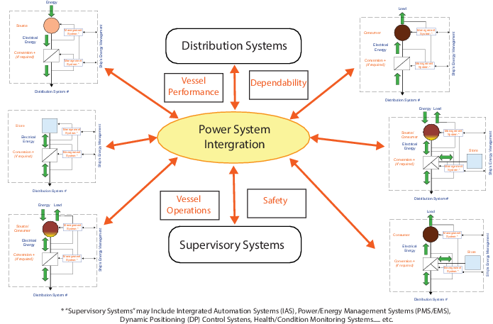
Figure 2.24.8 Role of system integration activities
24.3.11 Dependability: Dependability is as defined in IEC 60050(191), Quality vocabulary –
Part 3: Availability, reliability and maintainability terms – Section 3.2:
Glossary of international terms. It is the collective term used to
describe the availability performance and its influencing factors: reliability
performance, maintainability performance and maintenance support performance as
agreed with LR.
24.4 Hybrid electrical power system performance - System functional requirements
24.4.1 To provide sufficient electrical power of appropriate dependability to supply the
required essential services, habitability requirements and those services required
to maintain the ship in a normal sea-going and operational state during defined
operational conditions without recourse to the emergency electrical supply.
24.4.2 Damage and injury: To provide electrical systems and equipment with suitable
protection under fault conditions to prevent the following:
- injury to onboard personnel;
- damage to the equipment itself; and
- damage to equipment connected to it.
24.4.3 On ships with electric propulsion, to provide sufficient electrical power necessary
for an effective and agreed level of propulsion power during all normal and
reasonably foreseeable abnormal operational conditions.
24.5 Hybrid electrical power system performance - System performance targets
24.5.1 For Hybrid Power notation the performance of the system is to be such that in
the event of a single failure operation of the system may be interrupted but is to
be recoverable to a defined state bounded by time and magnitude.
24.5.2 For Hybrid Power (+) notation the performance of the system is to be such that
in the event of a single failure operation of the system is to be uninterrupted with
any degradation of performance agreed between the designers and Owners.
24.5.3 The hybrid electrical power system performance targets in all modes of operation are
to be defined and agreed between the designers and Owners.
24.5.4 The electrical system design maximum and minimum operating voltage and
input frequency together with acceptable limits of excursions are to be specified by
the system designer and are to be in compliance with the requirements of the
Rules.
24.5.5 Specific consideration is to be given to time-based performance targets for systems
in which stored electrical energy supplies any part of the ship’s main power demand.
24.5.6 Methods of verification of actual performance against targets are to be defined and
are to cover all phases of the lifecycle.
24.6 Hybrid electrical power system performance - Dependability principles
24.6.1 The hybrid electrical power system dependability principles are to be defined and
agreed between the designers and Owners consistent with the requirements for
Hybrid Power or Hybrid Power (+) notation.
24.6.2 The principles are to cover defined operating modes, all normal and reasonably
foreseeable abnormal operating and fault conditions and are to specifically consider
the fault ride-through capability of the system.
24.6.3 The principles are to cover failures in active components of any of the sources,
stores, consumers, distribution system and energy management forming the hybrid
electrical power system. Such components may include, but are not restricted to, the
following:
- Prime movers (e.g. auxiliary engines);
- Generators and their excitation equipment;
- Gearing;
- Pumps;
- Fans;
- Switchgear and controlgear, including their assemblies;
- Thrusters; and
- Valves (where power actuated).
24.6.4 Consideration is to be given to other enabling systems not part of the hybrid
electrical power system whose failure or degradation could affect correct
functioning of the hybrid electrical power system (e.g. lubrication, cooling and
ventilation systems).
24.6.6 Arrangements are to ensure that the supply of essential services is not disrupted by
the unavailability of the largest source of electrical power and are to be in
accordance with a clearly described, documented and agreed redundancy design
intent.
24.6.7 The size and rating of electrical energy stores is to be appropriate for the
specified lifetime when subjected to in-service cyclic loading. Calculations
supporting this assessment are to be provided to LR.
24.6.8 For Hybrid Power (+) a hybrid electrical power system dependability assessment
is to be undertaken and submitted to LR. The objectives of the assessment are to:
- demonstrate the dependability of the system during all
normal and reasonably foreseeable abnormal conditions; and
- demonstrate that an appropriate level of dependability is
achieved that is commensurate with that agreed between the designers and
Owners.
The assessment shall be undertaken to a recognised standard that is acceptable to LR
(e.g. IEC 60300-3-1, Dependability management Part 3-1: Application guide –
Analysis techniques for dependability – Guide on methodology).
24.7 Hybrid electrical power system performance - Main source of electrical power
24.7.2 Any type of source of electrical power as detailed in these hybrid electrical power
system Rules may, subject to the approval of LR, be considered as having equivalent
function to that of a generating set as described in, but not limited to, Pt 6, Ch 2, 2 Main source of electrical power.
24.7.3 Sources of electrical power not forming part of the ship's main source of electrical
power may be used as an additional source of electrical power to supply electrical
services required for normal operational and habitable conditions provided that:
- The quality of power supplies meets the requirements of
Pt 6, Ch 2, 24.17 Transversal requirements 24.17.3; and
- Automatic arrangements are provided to start and connect
within a period not exceeding 45 seconds one of the sources forming the main
source of electrical power in the event of a single failure or the quality of
power supplies exceeding limits.
24.8 Hybrid electrical power system performance - Emergency source of electrical power
24.8.2 For ships with a specified service notation as defined in Pt 1, Ch 2, 2.3 Class notations (hull), where it is proposed
that a dedicated emergency source of electrical power and its associated
transitional source of power will not be provided, the main source of electrical
power and associated equipment is to meet the following requirements:
- Sources providing the main source of electrical power are to be:
- separated and located in two or more compartments
that are not contiguous with each other;
- self-contained and arranged to be independent such
that each system can operate without recourse to the other main
source(s) including power distribution and any associated auxiliary and
ancillary converting equipment and control systems;
- arranged such that a fire, flood or casualty in any
one of the compartments will not affect the electrical power
distribution from the other(s), or to the services required by Pt 6, Ch 2, 3 Emergency source of electrical power;
- capable of being started automatically on loss of
the power supplied by the other main source(s) of electrical power and
supplying the essential services as quickly as is safe and practicable
subject to a maximum of 45 seconds, or provided with a transitional
source of emergency electrical power;
- arranged to allow for maintenance at sea of any one
source without affecting the ability to comply with these requirements;
and
- provided with starting arrangements compliant with
the requirements of Pt 5, Ch 2, 9.5 Starting of the emergency source of power.
- Where these Rules specify that a service is required to be
connected to both the main and emergency source of electrical power or is to be
connected to the emergency switchboard, then these services are to be served by
at least two individual circuits from the separated main sources of electrical
power with arrangements to transfer between the two sources. The supplies are to
be separated in their switchboard and throughout their length as widely as is
practicable without the use of common feeders, protective devices, control
circuits or controlgear assemblies so that any single fault will not cause the
loss of both supplies.
- Provision is to be made for periodic testing to demonstrate
services required by Pt 6, Ch 2, 3 Emergency source of electrical power can
be supplied automatically following the loss of one main source of electrical
power.
- To demonstrate compliance with these requirements a risk
assessment of the electrical, mechanical, piping arrangements, cooling
arrangements and any other sub-systems whose failure or degradation could have
an impact on the performance of the system is to be carried out demonstrating
that a single point failure such as a fire or flooding within a space would not
render the systems incapable of supplying those services required in an
emergency or other reasonably foreseeable abnormal event. The assessment is to
be undertaken to a recognised standard that is acceptable to LR (e.g. ISO 31010,
Risk management – Risk assessment techniques) and in accordance with
ShipRight Procedure Risk Based Certification (RBC) .
24.9 Hybrid electrical power system performance - External source of electrical power
24.9.2 Arrangements for d.c. external sources are to comply with a recognised standard that
is acceptable to LR.
24.9.4 Ships using an external source of power to charge onboard stores of electrical energy
will be specifically considered by LR. Details of the arrangements and their
interfaces to ship systems are to be submitted.
24.10 Hybrid electrical power system performance - Electrical power supply to ship propulsion and ship positioning systems
24.11 Hybrid electrical power system components - Source of electrical power
24.11.6 Converters within power sources are to comply with Pt 6, Ch 2, 10.2 Semiconductor converters and the following
requirements:
- Converters are to be selected to withstand the voltage
ripple levels present on the distribution system. For every system, the
following voltage parameters are to be defined:
- maximum non-repetitive peak;
- maximum repetitive peak; and
- maximum repetitive peak-to-peak.
- Where pulse width modulation converters are to be used, the
voltage rate of rise times are to be determined, the results recorded and
submitted to LR. Rotating machinery, surge protective devices, cable insulation
and motor windings are to be designed accordingly.
- Converters may be of conversion type a.c./a.c., d.c./a.c.,
a.c./d.c., d.c./d.c., and of the controlled (e.g. active front end (AFE)) or
non-controlled type (e.g. diode supply unit (DSU)).
- Converters are to be provided with visual status indication
at their associated control stations to include, but not be limited to:
- Power available at the input;
- Power at output;
- Temperature; and
- Overload.
If certain indicators and alerts are not applicable,
sufficient evidence to support the claim is to be submitted for
consideration by LR. Additional indicators, alerts and shutdowns may be
necessary as determined through the system Failure Modes and Effects
Analysis (FMEA) required by Pt 6, Ch 2, 24.27 Power system development and integration - System Failure Modes and Effects Analysis (FMEA).
- Converters supplying electrical power to the distribution
system and consumers are to be capable of delivering the required currents for
the time required to enable current-time discrimination of protective devices to
operate. The electrical output of the converter is to be automatically restored
following fault clearance.
- Converter software is to satisfy the requirements of Pt 6, Ch 1, 2 Essential features for control, alarm, monitoring and safety systems
- Converters are to be capable of handling voltage and current
spikes from the distribution system under all normal and reasonably foreseeable
abnormal conditions without sustaining any damage or tripping.
- Converters supplying essential services are to automatically
restart and connect to the distribution system after a blackout as specified in
Pt 6, Ch 2, 2.2 Number and rating of generators and converting equipment.
- Where converters are equipped with internal capacitors which
can contribute significantly to the short-circuit level of the system, the
contribution is to be included in the design of the protection and distribution
system.
- The risk of converter component damage due to inrush
currents is to be minimised by appropriate management of these currents during
transient events and after short circuit.
- Where capacitors are connected to a converter output, the
output is to be charged by the converter or by external chargers to a level
which will minimise the risk of damage to the capacitors before connecting them
to the distribution system.
- Converters arranged to operate in parallel are to be capable
of stable load sharing up to maximum continuous load and inclusive of any
temporary overloads within their design rating.
- Where converters are arranged to provide protection against
electrical faults a disconnector or switch disconnector is to be provided to
enable safe isolation of the converter from its incoming supplies.
- Converters are to be protected from permanent physical
damage as a result of short circuits or overload currents on their input and
output terminals.
- Converters are to have a ride-through capability to manage
system transients including the effects of fault clearance in the distribution
system that is consistent with the dependability requirements of the
system.
- Converters are to be provided with appropriate filters to
ensure the required quality of power supply at both their input and output. In
the event of filter circuit failure, continued safe operation of the hybrid
electrical power system is to be possible by following specified procedures as
described in operation procedures. These procedures are to include any
operational limitations, and they are to be kept on board, maintained in
accordance with Pt 6, Ch 2, 24.18 Power system development and integration - General 24.18.3 and made available to the Surveyor on
request.
24.12 Hybrid electrical power system components - Store of electrical energy
24.12.1 Functional requirements: To provide sufficient stored electrical energy as a
component of the main source of power to supply services during normal and
reasonably foreseeable abnormal and emergency conditions.
24.12.2 Batteries of the vented and valve-regulated sealed type and lithium batteries are to
comply with Pt 6, Ch 2, 12 Batteries.
24.12.4 For consideration as a component of the main source of power on a ship with a
specified service notation as defined in Pt 1, Ch 2, 2.3 Class notations (hull) and subject to
approval of the National Administration a store of electrical energy is to:
- Comply with Pt 6, Ch 2, 24.7 Hybrid electrical power system performance - Main source of electrical power;
- Have a minimum capacity at any stage of its lifecycle
sufficient for its contribution to the main source of power that is necessary to
achieve the specified service requirements;
- Be provided via energy management functionality with remote
indication of state of charge (available capacity in a store expressed as a
percentage of rated capacity) and state of health (general condition of a store
expressed as a percentage of its ability to deliver the specified performance
compared with that of a new store);
- Have a primary purpose of supplying the ship’s main power
demand. Details of any secondary purpose including but not limited to optimising
performance (e.g. load smoothing, peak shaving), improving stability (e.g.
dynamic response) or providing transitional power are to be provided to LR;
and
- Be capable of being restored from a dead-ship condition with
no dependence on other systems or electrical supplies. Details of alternative
arrangements may be submitted for consideration by LR.
24.12.5 For consideration as an additional source of power a store of electrical energy is
to:
- Comply with Pt 6, Ch 2, 24.7 Hybrid electrical power system performance - Main source of electrical power 24.7.3;
- Be provided via energy management functionality with remote
indication of state of charge (available capacity in a store expressed as a
percentage of rated capacity) and state of health (general condition of a store
expressed as a percentage of its ability to deliver the specified performance
compared with that of a new store); and
- Have a primary purpose of supplying the ship’s main power
demand. Details of any secondary purpose including but not limited to optimising
performance (e.g. load smoothing, peak shaving), improving stability (e.g.
dynamic response) or providing transitional power are to be provided to LR.
24.12.7 Electrical energy storage devices connected to and charged by the distribution system
are to be protected against the defined effects of electrical faults in the
system.
24.12.8 Energy stores connected to and charged by the distribution system are to be so
located and provided with arrangements allowing for the safe isolation of their
terminals and the reduction of voltages to a safe level during maintenance or
provided with alternative arrangements providing an equivalent level of safety which
will be subject to special consideration.
24.12.9 Energy stores are to be connected to the distribution system by protection devices
which include but are not limited to overcurrent and short circuit protection. The
protective devices used are to be selective, ensuring faults are not transmitted
further, independent of the direction of current flow.
24.13 Hybrid electrical power system components - Consumer of electrical power
24.13.1 Functional requirements: To convert electrical power supplied from the hybrid power
generation and distribution system into useful work.
24.13.4 Where a converter is arranged to step down voltage to provide a lower voltage supply
to consumers than that of the power system, then arrangements are to be provided to
ensure the lower voltage distribution consumers are not subjected to voltage
variations, including fast transients, outside their safe operating regions.
24.14 Hybrid electrical power system components - Combined sources of electrical power, stores of electrical energy and consumers
of electrical power
24.14.1 Functional requirements: To provide the combined functional requirements of each of
the elements (sources, stores, consumers) from which the combination is
constructed.
24.15 Hybrid electrical power system components - Distribution system
24.15.1 Functional requirements:
- To provide a dependable interconnection between sources,
stores and consumers of electrical power; and
- To distribute electrical power safely to consumers.
24.15.2 Arrangements for isolation and switching are to be provided which are to enable safe
isolation of faults and for maintenance.
24.15.3 Distribution systems supplying consumers through converters are to provide galvanic
isolation and ground separation.
24.15.5 Where consumers are supplied via converters which are connected to both sides of a
distribution system that is capable of being split, arrangements are to be provided
to eliminate the risk of current being supplied back to the distribution system for
example through flyback diodes.
24.15.6 Converters connecting sources, stores and consumers connected to the distribution
system are to facilitate the connection and removal of sources, stores and consumers
in a stable manner with the electrical power system in operation.
24.15.7 Converters are to be designed to prevent damage to the converter when switching under
load.
24.15.8 Where essential services are required by Pt 5 Main and Auxiliary Machinery to be duplicated, these are to be served by
individual circuits, separated in their switchboard or section board and throughout
their length as widely as is practicable without the use of common feeders,
protective devices, control circuits or controlgear assemblies, so that any single
fault will not cause the loss of both services.
24.15.9 The distribution system is to be split into at least two independent systems each
capable of independent operation or is to be separated by protection devices that
are selective, ensuring faults are not transmitted further, and operate independent
of the direction of current flow.
24.15.10 The distribution system is to be protected against electrical faults
including short circuit, overload, earth fault, differential current, under/over
voltage, under/over frequency, power quality, current and voltage imbalance and arc
fault in compliance with the relevant requirements of Pt 6, Ch 2, 6 System design – Protection and Pt 6, Ch 2, 24.15 Hybrid electrical power system components - Distribution system 24.15.11 to Pt 6, Ch 2, 24.15 Hybrid electrical power system components - Distribution system 24.15.14.
24.15.11 Active components may be used for the limitation of fault currents
subject to verification in a real environment of the performance of the component
under all normal and reasonably foreseeable abnormal operating and fault conditions
and subject to establishment of effective surveillance and periodic test procedures
during operation and maintenance in the ship’s operating manuals to verify the
component is capable of performing its intended function. An isolation device is to
be provided within the component and this is to be tripped automatically in the
event of the component operating. A risk assessment of the component is to be
undertaken to a recognised standard that is acceptable to LR (e.g. ISO 31010,
Risk management – Risk assessment techniques) and in accordance with
ShipRight Procedure Risk Based Certification (RBC).
24.15.12 Where energy management functionality provides protection against incorrect or
unexpected energy flows between the sources, stores and consumers forming part of
the hybrid electrical power system the sensors used for this purpose in the
distribution system are to be independent of those used for control, monitoring and
safety systems.
24.15.13 Where a bi-directional flow of power may occur, the distribution system is to
withstand the power variations being introduced. The level of bi-directional flow
allowed is to be specified by the system designer.
24.15.14 For Hybrid Power (+) notation facilities are to be provided for automatic
detection of the location of insulation breakdown with respect to earth of equipment
and distribution systems to a level determined by the integrator consistent with the
system’s dependability targets and agreed with the designers and Owners.
24.15.17 Where fuses are implemented to limit the fault current in the converter, the
activation of the protection is not to influence redundant consumers or cause loss
of other single consumers as required by Pt 6, Ch 2, 5.2 Essential services.
24.15.18 Fuses used to protect distribution converters are to be of the bolted type. Where
alternative arrangements are proposed, it is to be demonstrated that protection
system’s selectivity is not adversely affected as a result of an increased
connection resistance.
24.15.19 For each section of a d.c. bus there is to be at least one voltmeter per section. An
ammeter is to be provided for each converter supplying a d.c. bus. Similar
arrangements are to be provided for screen-based displays.
24.15.21 Power quality assessments are to consider the detection and impacts of circulating
currents such as may exist through capacitive coupling in semiconductor
converters.
24.15.22 Constant current distribution systems will be subject to special consideration and
are not covered by these Rules.
24.15.23 For Hybrid Power (+) notation warnings of degrading power quality
are to be provided and in the event of power quality exceeding prescribed limits
automatic isolation and reconfiguration of the power system is to occur as agreed
between the designers and Owners.
24.16 Hybrid electrical power system components - Energy management
24.16.1 Functional requirements:
- To ensure that sufficient energy is available to satisfy the
main power demand under all foreseeable operational conditions.
- To inform Operators as soon as reasonably practicable of
deviations from normal operation of the hybrid electrical power system under all
normal and reasonably foreseeable abnormal operational conditions.
- To initiate immediate corrective action on detection of
component faults in the hybrid electrical power system that present a danger,
reducing the risk to a level that is acceptable to LR.
- To provide functionality beyond the scope of conventional
power management that is necessary for the control, monitoring, protection and
dependability of the hybrid electrical power system.
24.16.4 Loss of energy management functionality is not to compromise the supply of main
power, the safety of the ship, the hybrid electrical power system, or its
components.
24.16.5 Energy management functionality is to include, but not be limited to, the
following:
- Control (of the complete system and of each of its
sub-systems):
- Hybrid electrical power system operating mode
selection and transition;
- Connection and disconnection of sources, stores and
consumers to the distribution system in response to operating conditions
and prevailing loads;
- Connection and disconnection of distribution system
sections;
- Load allocation to and sharing between sources;
- Load restriction of consumers;
- Energy flow management;
- Distribution system a.c. voltage and frequency and
d.c. voltage; and
- Control functions required by sources, stores,
consumers or distribution system that are necessary for their operation
under all reasonably foreseeable normal, abnormal and fault
conditions.
- Alarm and monitoring:
- Mode transition status;
- Connection status of sources, stores, consumers and
distribution system sections;
- Energy flows within the hybrid electrical power
system and between its constituent parts;
- Power quality as detailed in Pt 6, Ch 2, 24.17 Transversal requirements 24.17.3; and
- For stores, state of charge and state of health as
defined in Pt 6, Ch 2, 24.12 Hybrid electrical power system components - Store of electrical energy 24.12.4 and Pt 6, Ch 2, 24.12 Hybrid electrical power system components - Store of electrical energy 24.12.5.
- Protection and safety:
- Blackout prevention;
- Blackout recovery;
- Detection of abnormal or unexpected energy flow as
described in Pt 6, Ch 2, 24.15 Hybrid electrical power system components - Distribution system 24.15.13; and
- Safety functions required by sources, stores,
consumers or distribution system that are necessary for their safe
operation.
24.16.6 Overall ship-wide energy management functionality is to be integrated and coordinated
with the functionality of the local management systems as described in Pt 6, Ch 2, 24.3 Definitions for each of the components
(sources, stores, consumers, combinations, distribution system) of the hybrid
electrical power system and is to ensure safe operation of the ship under all normal
and reasonably foreseeable abnormal operating and fault conditions.
24.16.7 Additional energy management functionality for Hybrid Power (+) notation is to
consider, but not be limited to, the following. The level of functionality supplied
is to be consistent with the enhanced performance and dependability required by the
system.
- Control (of the complete system and of each divisible
element):
- Automatic configuration of the power system based on
predicted energy flow;
- Automatic system isolation and reconfiguration such
that, in the event of a single failure in electrical power sources,
stores, distribution system or associated control systems, the impact on
the operational performance of the ship is as agreed with LR and there
is no impact on the ship’s ability to complete its mission;
- System performance optimisation, independent of
primary control functions covering emissions, efficiency, availability,
reliability or operating cost; and
- Control of stores with load smoothing, peak shaving,
dynamic response or other optimisation capability.
- Alarm and monitoring:
- Degradation of power quality;
- Remaining time for continued operation of the power
system at current operating conditions and levels of power consumption.
This may take the form of a real-time performance capability plot;
- System performance covering energy consumption,
emissions, efficiency, availability, reliability or operating cost;
and
- Health and condition of hybrid electrical power
system components including the effects of ageing on electrical energy
storage devices.
- Protection and safety:
- Automatic isolation and reconfiguration of the power
system on detection of abnormal energy flow;
- Consequence analysis determining the remaining time
for continued operation of the power system under stated operating and
load conditions following the most significant single failure. This may
take the form of an onboard off-line simulation derived from, or an
integral element of, the simulation described in Pt 6, Ch 2, 24.23 Power system development and integration - Energy flows 24.23.3; and
- Automatic detection of faults detailed in the system
level FMEA with display of mitigating actions.
24.17 Transversal requirements
24.17.1 All electrical equipment is to prevent injury to personnel or damage to other
equipment and is to be suitably protected against damage to itself under normal,
reasonably foreseeable abnormal and fault conditions.
24.17.2 The supply of electrical power sufficient for the correct operation of electrical
services for essential equipment and habitable conditions is to be maintained:
- during all normal and reasonably foreseeable abnormal
operating and fault conditions;
- irrespective of the direction of the propulsion shaft
rotation; and
- without any requirement to revert to emergency
supplies.
24.17.3 Hybrid electrical power systems are to provide a power quality as required by;
- Pt 5, Ch 2, 7.3 Auxiliary and emergency engine governors ,
- Pt 6, Ch 2, 1.8 Quality of power supplies,
- Pt 6, Ch 2, 2.4 Prime mover governors
and
- Pt 6, Ch 2, 9.4 Generator control
during all normal and reasonably foreseeable abnormal operating and fault
conditions.
24.17.4 A.c. and d.c. systems are during all normal and reasonably foreseeable abnormal
operating and fault conditions to provide a quality of power as required by a
recognised National or International Standard specified by the power system
integrator that is acceptable to LR.
24.17.6 The key parameters of power quality as determined by the system
integrator with agreement of the Owner and as applicable to the type of electrical
power system are to be monitored and recorded for each individually operable section
of the distribution system. An alarm is to be raised at a monitored operating
station in the event of power quality exceeding limits determined by the system
integrator in compliance with the power quality requirements of the Rules. A
description of the arrangements provided is to be submitted.
24.17.7 For either notation, all electrical equipment is to comply with the
requirements of Pt 6, Ch 2 Electrical Engineering including:
- General requirements - Pt 6, Ch 2, 1 General requirements including fire,
electric shock, ignition, radiation and environment;
- Creepage and clearance - Pt 6, Ch 2, 7.5 Creepage and clearance distances;
- Arc - Pt 6, Ch 2, 8 Protection from electric arc hazards within electrical equipment; and
- Explosive atmospheres - Pt 6, Ch 2, 14 Electrical equipment for use in explosive gas atmospheres or in the presence of combustible dusts.
24.17.8 The choice of materials and components of construction, as well as the design,
location and ship installation, are to be made according to the environmental,
maintenance and operating conditions in order to maintain the continued function of
the equipment during all normal and reasonably foreseeable abnormal conditions and
to reduce the risk of:
- injury to onboard personnel;
- damage to the equipment the system is contained within or
adjacent equipment and systems;
- damage to adjacent equipment and systems; and
- damage to the ship.
24.17.10 Electrical equipment is to be used within its designed operating
parameters, such as current, voltage, power, charging rate, energy storage, etc. to
prevent:
- a hazard occurring; and
- the equipment affecting safety functions.
24.17.11 All electrical equipment supplied from the main and emergency sources of electrical
power and electrical equipment for essential and emergency services is to be
selected to operate satisfactorily under the variations of voltage and ripple
frequencies which may be present in the system.
24.17.14 Interlocks or an alternative acceptable to LR are to be provided which will prevent
access to capacitors until their voltage level has reduced to below the safe extra
low voltage level (50 V); this is to ensure safety of personnel during
maintenance.
24.18 Power system development and integration - General
24.18.2 The activities should be based on the principles of the following five levels with
measures adopted at each level being, as far as practicable, independent of each
other:
- Prevention of abnormal operation and failures though design
and high quality in construction, operating rules and normal operating
procedures;
- Control of abnormal operation and detection of failures
through control, limiting and protection systems, monitoring/surveillance
features and abnormal/emergency operating procedures;
- Control of hazards within the system design to protect
against escalation to an incident or accident through engineered safety features
and emergency operating procedures;
- In support of and coordinated by the Owner and ship
designer, control of severe ship or infrastructure conditions that may exceed
the system design intent including prevention of hazard progression and
mitigation of hazardous consequences through complementary procedures and hazard
management; and
- In support of and coordinated by the Owner and ship
designer, mitigation of accident consequences through emergency response.
The system designer is to ensure adoption of principles (a) to (c) during
the development and integration of the hybrid electrical power system providing
evidence to LR through the documentation that is submitted for design review as
detailed in Pt 6, Ch 2, 1.2 Documentation required for design review 1.2.18.
24.18.3 At each phase of a project integration activities are to be managed by a suitably
competent single designated party and are to be carried out in accordance with a
defined procedure identifying the roles, responsibilities and requirements of all
parties involved.
24.18.4 Where the designated party changes during a project, then there is to be a full and
auditable transfer of necessary integration information between the parties.
24.18.5 Systems engineering processes are to comply with ISO 15288 Systems and Software
Engineering – System Life Cycle Processes or an acceptable equivalent
National or International Standard.
24.19 Power system development and integration - System operational concept
24.19.1 The system operational concept is to be defined including a description of how the
control, alarm and safety systems for the hybrid electrical power system provide
effective means for operation and control during all defined ship operational
conditions.
24.19.2 The system operational concept is to detail the capability, functionality and modes
of operation under defined operating and emergency conditions and is to be agreed
between the designers and Owners.
24.19.3 The system operational concept is to be submitted for design review.
24.20 Power system development and integration - Operating modes
24.20.1 Operating modes for the hybrid electrical power system are to be defined and agreed
between the designers and Owners.
24.20.2 Modes are to cover all normal and reasonably foreseeable abnormal operating and fault
conditions.
24.20.3 Modes are to be compatible with the ship’s overall operating modes.
24.20.4 The sequence of transition between operating modes is to be defined for all
reasonably foreseeable normal and abnormal operating and fault conditions.
24.20.5 A technical description is to be produced specifying for each of the ship’s possible
operating modes:
- the type of each electrical power source used to supply the
distribution system, such as a.c. generators, d.c. generators, converter,
batteries, fuel cells and photovoltaics;
- the operating mode of each electrical power source such as
constant voltage, constant current or variable voltage;
- the configuration of the electrical distribution system,
including the earthing and protection strategies to be used; and
- the worst-case failure design intent.
24.21 Power system development and integration - Consumer categorisation
24.21.1 Consumers supplied with electrical power from the hybrid electrical power system are
to be categorised according to their function and the services that they provide in
accordance with the requirements of Pt 6, Ch 2, 1.6 Definitions.
24.22 Power system development and integration - System components
24.22.1 The specifications for all components of the hybrid electrical power system (sources,
stores, consumers, distribution system, energy management) are to be validated by
the system designer for completeness and correctness in respect of the component’s
integration into the overall power system. Validated specifications are to be
submitted to LR.
24.22.2 Details of the following are to be specified:
- Operating modes and the transition between them;
- Control and monitoring functions;
- Mechanical components which might affect the hybrid notation
(e.g. cooling units with piping arrangements, pumps, valves, etc.);
- Safety functions;
- Failure modes;
- Isolation;
- Initial and through-life verification of conformance;
and
- Human element.
24.23 Power system development and integration - Energy flows
24.23.1 Energy flows within the hybrid electrical power system are to be determined for all
operating modes and all normal and reasonably foreseeable abnormal operating and
fault conditions.
24.23.2 The impact of transition between modes on energy flow is to be considered.
24.23.4 Simulation tools are to conform to appropriate National or International Standards
relevant to their use and are to have been validated in an equivalent
application.
24.23.5 The dynamic simulation is to be verified against the energy flows encountered during
the ship’s real performance to the extent that this is reasonably practicable.
24.23.6 Proprietary simulation tools not conforming to an appropriate National or
International Standard will be subject to special consideration. This consideration
will include:
- Pedigree of the underlying modelling platform on which the
simulation is built;
- Qualitative assessment of the simulation's functional
capabilities and model behaviours;
- Configuration management of the simulation model, its
architecture, functional blocks and the parameters on which it is based;
- Prior quantitative assessment of the simulation’s
performance in a similar application; and
- An engineering justification that the validation and
verification of the simulation is sufficient to enable its application in all
normal and reasonably foreseeable abnormal operating and fault conditions.
24.24 Power system development and integration - Power system analysis
24.24.1 The hybrid electrical power system is to be analysed for its electrical performance
under all defined operating modes and all normal and reasonably foreseeable abnormal
operating and fault conditions.
24.24.2 The analysis is to include, but not be limited to:
- Fault levels under short circuit conditions;
- Fault flows under short circuit and overload
conditions;
- Protection device operation, discrimination and
coordination;
- Quality of power supplies;
- Steady state performance;
- Transient performance;
- Earth fault currents;
- Resonance; and
- Common mode and circulating currents.
24.24.3 Information regarding the expected resistance, inductance and capacitance in the
system and the installed components is to be provided as part of the analysis study
as required by Pt 6, Ch 2, 1.2 Documentation required for design review.
The values chosen are to be based upon the component tolerances which result in the
worst case for each aspect of the analysis and are to be updated with actual values
when determined from component, sub-system or system test.
24.24.4 For Hybrid Power (+) notation the analysis is to be by a dynamic simulation
that can be exercised under all normal, abnormal and fault conditions, that is
maintained for the life of the ship and that can be exercised to verify operation of
the protection system including:
- Short circuit, single or multiple phases/poles;
- Overload;
- Overcurrent;
- Current imbalance;
- Voltage imbalance;
- Zone protection;
- Arc fault;
- Earth fault;
- Under/over voltage;
- Under/over frequency;
- Harmonic content;
- Quality of power supplies including degradation
detection;
- Energy flow including any regeneration by consumers;
- Resonance and stability;
- Transient impact of fault detection, clearance and
isolation;
- Transient impact of sources, stores and consumers being
tripped or shut down;
- Transient impact of load changes, both increase and
decrease; and
- Load sharing imbalance.
24.24.5 Simulation tools are to conform to appropriate National or International Standards
relevant to their use and are to have been validated in an equivalent
application.
24.24.6 The dynamic simulation is to be verified against the ship’s real performance to the
extent that this is reasonably practicable.
24.25 Power system development and integration - Safety functions
24.25.1 Safety functions related to the hybrid electrical power system and its constituent
parts are to be clearly defined covering their purpose, their functionality and
their location.
24.25.3 Safety functions including ESD, emergency stop and reversionary control procedures
for the hybrid electrical power system are to be defined, fully documented and made
available to the Operators, maintainers and regulatory authorities.
24.26 Power system development and integration - Risk assessment
24.26.1 Where the hybrid electrical power system introduces new technologies or topologies
not covered by the current Rules and Regulations then a risk assessment study is to
be carried out.
24.26.2 A formal method acceptable to LR is to be used to determine if new or significantly
greater hazards than those normally associated with the ship electrical power system
that would be mitigated by compliance with the Rules and Regulations have been
introduced (e.g. a preliminary hazard analysis or a structured checklist approach
(HAZID) in accordance with ISO 31010, Risk management – Risk assessment
techniques).
24.26.3 Where the results of this formal method establish that new hazards or
exist, the risk assessment study is to be undertaken to a recognised standard that
is acceptable to LR (e.g. ISO 31010, Risk management – Risk assessment
techniques) and in accordance with ShipRight Procedure Risk Based
Certification (RBC).
24.26.4 The objectives of the study are to:
- identify potential deviations from the intended operation of
the hybrid electrical power system;
- identify the causes of each deviation, and the consequences
for safety and dependability;
- list safeguards to minimise causes and consequences;
and
- determine and recommend if further safeguards should be
considered.
24.26.5 The scope of the study is to consider normal operation, start-up, normal shutdown,
non-use and emergency shutdown of the hybrid electrical power system.
24.26.6 The risk assessment technique(s) selected are to be appropriate for their intended
use and are to be accepted by LR.
24.27 Power system development and integration - System Failure Modes and Effects Analysis (FMEA)
24.27.1 An overall hybrid electrical power system FMEA is to be undertaken. The objectives of
the analysis are to identify:
- potential failures;
- consequences of failure on the hybrid electrical power
system and on ship operations;
- means to eliminate or prevent failure; and
- means to eliminate or minimise consequences.
24.27.2 The analysis may identify the requirement for safety measures in addition to those
specifically stated in these Rules. Where additional safety measures are identified,
evidence is to be provided that demonstrates how they are implemented and
validated.
24.27.3 As a minimum, the scope of the analysis is to consider the ‘fail safe’ condition,
location and arrangement of the critical system elements.
24.27.4 The analysis is to be undertaken to a recognised standard (e.g. IEC 60812,
Analysis techniques for system reliability – Procedure for failure mode and
effects analysis (FMEA)), or an equivalent and acceptable National or
International Standard.
24.27.5 The FMEA is to consider but not be limited to:
- Hidden faults that are not annunciated to or evident to the
Operator where a second subsequent fault can directly result in a significant
failure and hazardous condition;
- Foreseeable inadvertent operation of the hybrid electrical
power system;
- Failure to complete transition sequences (e.g. change of
operating mode or response to a fault including its detection, clearance,
isolation and reconfiguration);
- Items which can be dormantly failed and unavailable to
perform their intended operation on demand (e.g. normal to backup changeover
systems or standby start systems);
- Enabling systems not part of the hybrid electrical power
system (e.g. fuel supply, lubrication, cooling and ventilation systems) whose
failure could affect correct functioning of the hybrid electrical power
system;
- Sensor and feedback errors in programmable electronic
systems;
- Parameter corruption in programmable electronic systems
(e.g. incorrect scaling factors, control rates, alarm thresholds or trip
levels);
- Common cause effects in programmable electronic systems
(e.g. network storms in networked systems, power supply faults, time dependent
errors in operating systems with the potential to concurrently impact multiple
redundant control or monitoring systems);
- Common cause effects in electrical power systems (e.g. power
quality outside expected range or multiple earth faults in a parallel connected
system);
- Consequential failures resulting from a single failure that
are to be considered as an integral part of the single failure; and
- The viability of the role of the human in the detection and
mitigation of faults.
24.27.6 Examples of devices in which hidden failures can occur that are detrimental to the
dependability of a hybrid electrical power system include but are not limited
to:
- Protection devices – protection relays, dead-bus
sensing;
- Automatic isolation devices;
- Circuit breaker open/close/trip functions;
- Fault/current limitation devices;
- Arc detection;
- Load shedding devices;
- Safety devices;
- Fault detection systems;
- Alternator current boost systems;
- Interlocks and inter-trips;
- Automatic change-over systems, transfer and dual-feed
arrangements;
- Stand-by start arrangements;
- Transducers/sensors – giving an incorrect output;
- Slow processors (e.g. watchdog functions);
- UPS backed-up supplies; and
- Active failures of control systems – working but not doing
what was intended,
24.27.7 Hybrid electrical power system failure modes identified through the FMEA that could
impact the safe operation and performance of any component of the system
(source/store/consumer/combination/distribution system/energy management) are to be
notified to, and acknowledged by, the party accountable for the safety of the
component through an auditable process.
24.27.8 Component failure modes that could impact the safe operation and performance of the
hybrid electrical power system are to be notified to, and acknowledged by, the
hybrid electrical power system integrator through an auditable process.
24.27.9 For Hybrid Power (+) notation FMEAs for each of the key components of the
system may be requested by LR in support of the system FMEA.
24.28 Power system development and integration - Operating instructions
24.28.1 Operating Manuals are to be provided on board and submitted for information where
requested by LR. The manuals are to include, but not be limited to, the following
information:
- Particulars and a description of the systems;
- Operating instructions for the equipment and systems
(including fire isolation aspects);
- Maintenance instructions for the installed arrangements,
including procedures to prevent injury from electric shock and arc flash;
- Software configuration management procedures which are to
include a list of all versions of the software installed in the system, and the
settings, values of system or equipment specific configuration parameters;
and
- Output from the risk assessment processes that is necessary
for the safe operation of the system under all normal and reasonably foreseeable
abnormal operating conditions.
24.28.2 Overall hybrid electrical power system operating instructions are to be verified by
the system designer for their completeness and correctness in all operating modes
and for all foreseeable normal and abnormal operating and fault conditions. The
verified instructions are to be submitted to LR.
24.28.3 Consistency between the overall system instructions and those for each component of
the system is to be confirmed by the system designer.
24.28.4 All mitigating actions arising from the FMEA that require manual intervention are to
be confirmed as included in the operating instructions.
24.28.5 Procedures for reversionary (e.g. manual) control of the hybrid electrical power
system are to be included and are to be verified during practical operation.
24.29 Power system development and integration - Operator training
24.29.1 Training needs specific to the ship and necessary for its safe operation are to be
identified and documented in the ship’s operating manual.
24.29.2 For Hybrid Power (+) notation any ship-specific Operator training is to be
verified by the system designer for its completeness and correctness in all
operating modes and for all foreseeable normal and abnormal operating and fault
conditions with evidence of verification submitted to LR.
24.30 Power system development and integration - Through-life accountability
24.30.2 Proposed changes to the hybrid electrical power system including its components that
may impact on system safety or dependability are to be formally reviewed and
accepted by the system integrator before their incorporation with details submitted
to LR.
24.30.3 For Hybrid Power (+) notation details of incidents arising during any and all
operations of the hybrid electrical power system that has, or could have, resulted
in a hazardous consequence for people, platform or the environment are to be
monitored.
24.31 Verification requirements
24.32 Testing and trials
24.32.3 Materials are to be approved, manufactured and tested in accordance with a standard
acceptable to LR.
24.32.4 The fault ride-through capability of the system is to be demonstrated during
practical tests on the system.
24.32.5 Quality of power supply testing of the system and the components is to be carried out
to prove the equipment is capable of operating under the variations specified by the
hybrid electrical power system integrator and accepted by LR for all normal and
reasonably foreseeable abnormal operating conditions.
24.32.6 Where considered necessary by LR, additional testing may be required.
24.32.7 Satisfactory operation and load testing of the hybrid electrical power system in
harbour and during sea trials are to be witnessed by LR.
24.32.8 Measurements are to be taken as part of the trials to verify that the installation
will provide a quality of power supply in accordance with the values declared by the
hybrid electrical power system integrator as described in Pt 6, Ch 2, 24.17 Transversal requirements.
24.32.9 For Hybrid Power (+) notation additional trials are to be carried out to:
- Verify that the system delivers the determined levels of
performance as described in Pt 6, Ch 2, 24.5 Hybrid electrical power system performance - System performance targets;
- Verify that the system fulfils the redundancy principles defined by
the hybrid electrical power system integrator as described in Pt 6, Ch 2, 24.6 Hybrid electrical power system performance - Dependability principles;
- Verify the correct operation of the additional energy
management functionality described in Pt 6, Ch 2, 24.16 Hybrid electrical power system components - Energy management;
- Verify that the system performs in accordance with its
simulation(s) as described in Pt 6, Ch 2, 24.23 Power system development and integration - Energy flows and Pt 6, Ch 2, 24.24 Power system development and integration - Power system analysis; and
- Verify the findings of the FMEA analysis detailed in Pt 6, Ch 2, 24.27 Power system development and integration - System Failure Modes and Effects Analysis (FMEA) and the response of
the system to simulated failures.
|