
Section
6 Shell envelope framing
6.1 Longitudinal stiffening
6.1.3 Side
frames and end brackets of other structural configurations will be
specially considered.
6.2 Transverse stiffening
6.2.1 The
modulus and inertia of main and topside tank frames in the midship
region are to comply with the requirements given in Table 7.6.1 Shell framing. Arrangements of main
frames in holds in association with web frames are not recommended
in view of the vulnerability to cargo handling damage. Where such
web frames are proposed the arrangements and scantlings will be specially
considered.
6.2.2 Main
frames in the cargo and ballast holds are to have a web thickness
not less than:
-
In general:
or 13 mm whichever is the lesser
-
In the foremost hold:
|
t
min
|
= |
1,15 (7 + 0,03L) mm,
|
or 15 mm whichever is the lesser
where L is the Rule length, in metres.
6.2.3 The
web depth to thickness ratio of the frames is not to be greater than:
 , for symmetric sections , for symmetric sections
 , for asymmetric sections , for asymmetric sections
The breadth to thickness
ratio of the flange outstand is not to be greater than:

6.2.5 The
lengths of the arms of the brackets, measured as shown in Figure 7.6.1 Diagrammatic arrangement of end brackets, are not to be less than:
-
Frame connection
to hopper tank.
Athwartship arm:
Vertical arm:
-
Frame connection
to topside tank
Athwartship arm:
Vertical arm:
In no case are the bracket arm lengths to be taken less than
0,125H, where H is as defined in Table 7.6.1 Shell framing.
Table 7.6.1 Shell framing
| Location
|
Modulus, in cm3
|
Inertia, in cm4
|
| (1) Main frames in dry cargo
holds
|
Z = 3,50skh
T1
H
2 x 10⁻³
|
|
| (2) Main frames in cargo holds used
for water ballast
|
The greater of the following:
|
|
|
|
(a) Z = 1,15 x modulus given in (1)
|
|
|
(b) Z = 6,7skh
4
H
2 x 10⁻³
|
| (3) Transverse frames in
topside wing tanks
|
The greater of the following:
|
|
|
|
(a) 1,15 x Z as given in
location (1) of Table 1.6.3 Shell framing (transverse)
|
|
|
(b) As required by Pt 4, Ch 7, 7.3 Bulkhead stiffeners 7.3.1 for the sloped bulkhead
stiffeners
|
| Symbols
|
|
h
T1
|
= |
head, in metres, at middle of H
|
|
|
= |
 in metres, for frames where the mid-length of
frame is above the summer load waterline, in metres, for frames where the mid-length of
frame is above the summer load waterline, |
|
|
= |
 is not to be taken less than 0,7 is not to be taken less than 0,7 |
|
|
= |
(h
6 + C
w
 , in metres, where the mid-length of frame is
below the summer load waterline , in metres, where the mid-length of frame is
below the summer load waterline |
|
h
4
|
= |
head, in metres, measured from the middle of H
to the deck at side, or half the distance from the middle of
H to the top of the overflow, whichever is greater. |
|
|
h
6
|
= |
vertical distance in metres, from the summer load
waterline at draught T to the mid-length of H
|
|
C
w
|
= |
a wave head, in metres |
|
|
= |
7,71 x 10⁻²
Le
-0,0044L
|
|
|
= |
where e = base of natural logarithms 2,7183 |
|
|
= |
(1,0 + 0,0023 (L - 200)) for L > 200
m |
|
H
|
= |
length overall of frame, in metres, but is to be taken
not less than 2,5 m |
|
6.2.7 The
upper and lower integral or separate brackets are to have a web thickness
not less than the as built web thickness of the side frame. In addition,
the lower bracket thickness is to be not less than:
The toes of the brackets are to be designed to avoid
notch effects by making the upper and lower toes concave or otherwise
tapering them off, see also
Pt 3, Ch 10, 5.1 Continuity and alignment 5.1.7.
6.2.8 Except
as indicated in Pt 4, Ch 7, 6.2 Transverse stiffening 6.2.9, frames
are to be fabricated symmetrical sections with integral upper and
lower brackets.
The side frame face plate is to be curved (not knuckled) at
the connection with the end brackets. The radius of curvature, r,
is to be not less than:
where
|
b
f
|
= |
breadth of the bracket face plate, in mm |
|
t
f
|
= |
thickness of the bracket face plate, in mm |
The brackets are to be arranged with soft toes and the frame
section face bar tapered symmetrically to the toes with a taper rate
not exceeding 1 in 3. Where the free edge of the bracket is hollowed
out, it is to be stiffened or increased in size to ensure that the
section modulus of the bracket through the throat is not less than
that of the required straight edged bracket.
6.2.9 In ships
of length, L, less than 190 m, mild steel fabricated
frames may be asymmetric and fitted with separate brackets. Brackets
are to be arranged with soft toes. The free edges of the brackets
are to be stiffened as follows:
-
Where a flange
is fitted, its breadth, b
f, is to be not less
than:
or 50 mm, whichever is the greater
The flange is to be tapered at the ends with a taper rate not
exceeding 1 in 3.
-
Where the edge
is stiffened by a welded face flat, the cross-sectional area of the
face flat is to be not less than:
-
0,009 b
f
t cm2 for offset edge stiffening
-
0,014 b
f
t cm2 for symmetrically placed stiffening
where
|
t
|
= |
web
thickness of bracket, in mm |
The face plate is to be tapered at the ends
with a taper rate not exceeding 1 in 3.
6.2.10 For
mild steel construction with separate brackets where the frames are
lapped on to the bracket, the length of the overlap is to be adequate
to provide for the required area of welding to achieve equivalent
strength.
6.2.11 Double
continuous welding is to be adopted for the connections of frames
and brackets to side shell, hopper and topside tank plating and web
to face plates. For this purpose, the following weld factors are to
be adopted:
Where the hull form is such that an effective fillet weld cannot
be made, edge preparation of the web of the frame and bracket may
be required, in order to ensure the required efficiency of the weld
connection.
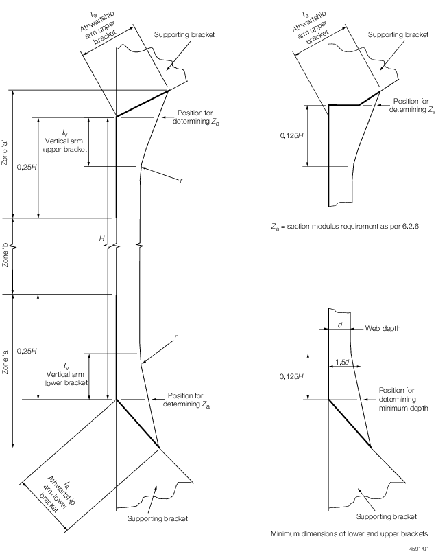
Figure 7.6.1 Diagrammatic arrangement of end brackets
6.2.12 Continuity
of the frames is to be maintained by supporting brackets, see
Figure 7.6.2 Supporting brackets in topside and hopper tanks, in the topside and hopper
tanks. The design of end connections and their supporting structure
is to be such as to provide adequate resistance to rotation and displacement
of the joint. For this purpose, in the hopper and topside tanks, the
thickness of the supporting brackets (which must align with the hold
main frame brackets) is to be not less than the following:
-
Lower brackets
(in hopper tank):
t = t
min + 0,5 mm, where t
min is derived from Pt 4, Ch 7, 6.2 Transverse stiffening 6.2.2 or
t = 9,0 mm
whichever is the greater.
-
Upper brackets
(in topside tank):
t = t
min, where t
min is derived from Pt 4, Ch 7, 6.2 Transverse stiffening 6.2.2 or
t = 9,0 mm
whichever is the greater.
The size and arrangement of stiffening of the supporting brackets
will be specially considered. Where the toe of the hold frame bracket
is situated on or in close proximity to the first longitudinal from
the shell of the hopper or topside tank sloped bulkheads, the supporting
brackets are to be extended to the next longitudinal. This extension
is to be achieved by enlarging the supporting bracket or by fitting
an intercostal flat bar stiffener the same depth as the longitudinal
and connected to the webs of the longitudinals.
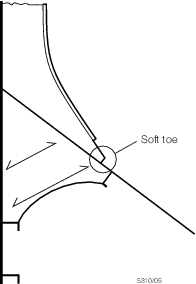
Figure 7.6.2 Supporting brackets in topside and hopper tanks
6.2.13 The
requirements are to be maintained throughout the cargo hold region.
However, in the forward and aft cargo holds where the shape becomes
finer because of the ship form, increased requirements may be necessary
and each case will be specially considered.
6.2.15 The
hold side shell frame adjacent to the collision bulkhead is to be
suitably strengthened. As an alternative, at least two supporting
structures are to be fitted which align with the forepeak stringers
or flats, see
Figure 7.6.4 Hold frame supporting structures at fore end of No. 1 cargo hold.
The supporting structures are to have adequate cross-sectional shear
resisting area at their connections to the hold frame.
6.2.16 Detail
design guidelines for connection of side shell frames to hopper and
topside tank plating are shown in the Shipright FDA Procedure,
Structural Detail Design Guide (SDDG).
6.3 Primary supporting structure
6.4 Additional requirements for ships not built to the IACS Common Structural Rules
6.4.1 Bulk Carriers not built to the IACS Common Structural Rules are to comply with the
requirements of this sub-Section.
6.4.2 For ships with single side structures, the material grade of the lower bracket of
side frame shall not be less than grade D/DH.
6.4.3 The safety factor with respect to lateral buckling of transverse ordinary stiffeners
is to be 1,15 and calculated in accordance with the ShipRight Guidance Notes for
ShipRight SDA Buckling Assessment.
|