
Section
6 Hull requirements for first-year ice conditions – Ice Classes
1AS FS, 1A FS, 1B FS, 1C FS and 1D
6.1 General
6.1.1 In addition
to the requirements of the Finnish-Swedish Ice Class Rules,
the following Sections are to be complied with for Ice Class
1AS FS, Ice Class 1A FS, Ice Class 1B FS, Ice Class 1C FS and Ice Class 1D, where applicable.
Alternative arrangements to attain similar performance will be considered.
6.2 Framing – General requirements
6.2.1 Where
a frame intersects a boundary between two of the hull regions the
scantling requirements applicable will be those for the forward region
if the forward midship boundary is intersected or for the midship
region if the aft midship boundary is intersected.
6.2.2 The
effective weld area attaching ice frames to primary members is not
to be less than the shear area for the frames.
6.2.3 Asymmertrical
frames and frames which are not at right angles to the shell (web
less than 90 degrees to the shell) shall be supported against tripping
by brackets, intercostals, stringers or similar, at a distance not
exceeding 1300 mm. For Ice Class 1D, the distance may
be increased to 2000 mm. For frames with spans greater than 4 m the
extent of anti-tripping supports is to be applied to all regions.
For frames with spans less than or equal to 4 m the extent is to be
as given in Table 2.6.1 Extent of anti-tripping
supports. FEA
may be carried out to demonstrate equivalent support of alternative
arrangements.
Table 2.6.1 Extent of anti-tripping
supports
| Ice Class
|
Extent of anti-tripping
supports
|
|
1AS FS
|
All regions
|
|
1A FS
|
Forward and midship
regions
|
|
1B FS
|
Forward region
|
|
1C FS
|
Forward region
|
|
1D
|
Forward region
|
6.3 Primary longitudinal members supporting transverse ice framing
6.3.1 The
webs of primary longitudinal members supporting transverse ice frames
are to be stiffened and connected to the main or intermediate frames
so that the distance, r, between such stiffening is not
to be greater than given according to the following formula:
|
r
|
= |

|
where
|
t
|
= |
thickness,
in mm, of the primary longitudinal member adjacent to the shell plating |
|
γ |
= |
 |
|
|
= |
 |
or
|
γ
|
= |
1,0, whichever is the least |
(b) Midship and aft regions
|
γ
|
= |

|
or
|
γ |
= |
1,0, whichever is the least |
6.3.2 The
minimum thickness of the web plating of longitudinal primary members
is to comply with the requirements of Pt 3, Ch 10, 4 Construction details for primary members.
Table 2.6.2 Longitudinal distribution factor
αo
| Ice Class
|
αo
|
| Forward
|
Midship
|
Aft
|
|
1AS FS
|
1,00
|
0,98
|
0,89
|
|
1A FS
|
0,87
|
0,75
|
0,64
|
|
1B FS
|
0,78
|
0,64
|
0,51
|
|
1C FS
|
0,68
|
0,53
|
0,37
|
|
1D
|
0,68
|
—
|
—
|
6.4 Stem
6.4.1 The
stem is to be made of rolled, cast or forged steel or of shaped steel
plates. A sharp edged stem, as shown in Figure 2.6.1 A sharp edged stem, improves the manoeuvrability of the ship in ice.
Where a sharp angle stem is fitted, the section modulus as given in Pt 8, Ch 2, 6.4 Stem 6.4.2 and Pt 8, Ch 2, 6.4 Stem 6.4.3 is to apply to the stem section
only, otherwise the section modulus may be applied including side
plates.
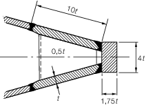
Figure 2.6.1 A sharp edged stem
6.4.2 The
section modulus of the stem in the fore and aft direction is not to
be less than determined in accordance with the following formula:
where
6.4.3 The
dimensions of a welded stem constructed as shown in Figure 2.6.1 A sharp edged stem are to be determined
in accordance with the following formula:
|
t
|
= |
 mm mm
|
where
|
t
|
= |
thickness
of the side plates, in mm. |
6.4.4 In bulbous
bow constructions, the extent of plating below the Ice Light Waterline
should be such as to cover that part of the bulb forward of the vertical
line originating at the intersection of the Ice Light Waterline and
the stem contour at the centreline. A suitably tapered transition
piece should be arranged between the reinforced stem plating and keel.
However, in no case should the reinforced stem plating extend vertically
below the Ice Light Waterline for less than 750 mm. The adjacent strake
to the reinforced shaped stem plating of the bulb should be in accordance
with the requirements for shell plating.
6.4.5 Where
in the ice belt region the radius of the stem or bulb front plating
is large, one or more vertical stiffeners are to be fitted in order
to meet the section modulus requirement of Pt 8, Ch 2, 6.4 Stem 6.4.2. In addition, vertical ring
stiffening will be required for the bulb.
6.4.6 The
dimensions of the stem may be tapered to the requirements of Pt 3, Ch 5, 3.3 Stem at the upper deck.
The connections of the shell plating to the stem are to be flush.
6.5 Stern
6.6 Renewal criteria within ice strengthening area for CSR ships
6.6.1 For
double hull oil tankers and bulk carriers that are compliant with
the IACS Common Structural Rules for Bulk Carriers and Oil Tankers
(CSR) , the renewal criteria of the local structure for general
corrosion is to be calculated in accordance with the applicable CSR
renewal criteria.
6.7 Rudder and steering arrangements
6.7.1 Rudder
scantlings, posts, rudder horns, solepieces, rudder stocks, steering
engine and pintles are to be dimensioned in accordance with Pt 3, Ch 6 Aft End Structure and Pt 3, Ch 13 Ship Control Systems as appropriate. The speed used in the calculations is to be
the maximum service speed or that given in Table 2.6.3 Minimum speed, whichever is the greater.
When used in association with the speed given in Table 2.6.3 Minimum speed, the rudder profile
coefficients are to be taken as 1,1.
Table 2.6.3 Minimum speed
| Ice
Class
|
Minimum speed,
|
| in knots
|
|
1AS FS
|
20
|
|
1A FS
|
18
|
|
1B FS
|
16
|
|
1C FS
|
14
|
|
1D
|
14
|
6.7.2 For double plate rudders, the minimum thickness of plating and horizontal
and vertical webs is to be determined as for shell plating in the midbody region. For
the horizontal and vertical webs, the corrosion-abrasion increment, need not be added.
For Ice Class 1D, the minimum thickness of plating and webs, of double plate
rudders and the extent of application are to be determined as for those in Ice Class
1C FS.
6.7.3 Where an ice class notation is included in the class of a ship, the nozzle
construction requirements, as defined in Table 13.3.1 Nozzle constructionin Pt 3, Ch 13 Ship Control Systems, are to be upgraded to include abrasion allowance as
follows:
| Ice Class
|
Thickness increment
|
|
1AS FS
|
5 mm
|
|
1A FS
|
4 mm
|
|
1B FS
|
3 mm
|
|
1C FS
|
2 mm
|
|
1D
|
2 mm
|
However, the thickness of the shroud
plating is not to be less than the shell plating for the aft region
taking frame spacing s in the formula as 500 mm.
6.7.4 The scantlings of the stock, pintles, gudgeon and solepiece associated with
the nozzle are to be increased on the basis given in Pt 8, Ch 2, 6.7 Rudder and steering arrangements 6.7.1. However, the diameter of the nozzle stock is to be
not less than that calculated in the astern condition taking the astern speed as half
the speed given in Table 2.6.3 Minimum speed or the actual astern speed, whichever is the
greater.
6.7.5 Nozzles
with articulated flaps will be subject to special consideration.
6.7.6 For
the Ice Classes 1AS FS and 1A FS, the rudder
stock and the upper edge of the rudder shall be protected against
ice pressure by an ice knife or equivalent means. The ice knife is
to extend down to the ice light waterline; this requirement may be
waived where this would lead to impracticable ice knifes, e.g. for
ships with large draught variations.
6.7.7 For
the Ice Classes 1AS FS and 1A FS, due regard
is to be paid to the excessive load caused by the rudder being forced
out of the midship position when backing into an ice ridge. When vessels
are intended to operate with significant time in astern operation,
then the hull strength is to be based on the method used in the forward
region; however, due consideration may be given to the anticipated
power in this mode of operation.
|