
Section
3 Stress analysis model
3.1 General
3.2 Stress determination in primary members
3.2.1 Primary
members are major structural members and provide support to decks,
major equipment, etc. and also control the cross-sectional and longitudinal
shape between decks, side shell and bulkheads. The major primary members
are listed in the paragraphs below.
3.2.2 The
following structural items are classed as longitudinal primary members:
- Double bottom girders with attached bottom shell and inner bottom
plating.
- Single bottom girders with attached bottom shell plating.
- Deck girders.
- Longitudinal stringers with attached side shell or longitudinal
bulkhead plating.
- Horizontal diaphragms with attached side shell and inner skin
plating.
3.2.3 The
following structural items are classed as vertical primary members:
- Deep web frames supporting the side shell or bulkheads including
attached plating.
- Double skin web frames including the attached side shell and inner
skin plating.
- Deep vertical bulkhead stiffeners.
3.2.4 The
following structural items are classed as transverse primary members:
- Double bottom floors with bottom shell and inner bottom plating.
- Single bottom floors with bottom shell plating.
- Deep deck or transverse beams with attached deck plating.
- Double skin deck beam with attached upper and lower deck plating.
- Transverse bulkhead stringers with attached bulkhead plating.
3.2.5 Primary
members support the secondary members and can be considered to act
independently of the secondary members. They need to be considered
as a large beam supporting local loads with the global and local membrane
stresses in the attached plating.
3.2.7 The
stresses in primary members are to be derived using the recommended
equations and stiffener end conditions given in Table 3.3.1 Stress determination in primary
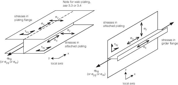
members The stress components
used in deriving the primary member stresses are given below.
Table 3.3.1 Stress determination in primary
members
| Stress direction
|
Stress equation
|
Stiffener end
condition
|
Notes
|
| Longitudinal primary members
|
| σx
|
σx = σhg + σxb N/mm2
|
Built in
|
Applicable to the flange and the
attached plating
|
| σy
|
σy = σyg N/mm2 (attached to deck
plating)
σy = σxv N/mm2
(attached to side shell or long bhd plating)
|
N.A.
|
Only applicable to the attached
plating
|
| τxy
|
τxy is to be taken as the shear stress for the attached
plating, see
Vol 1, Pt 7, Ch 3, 3.3 Stress determination in primary/secondary systems or Vol 1, Pt 7, Ch 3, 3.4 Stress determination in grillage systems
|
—
|
Only applicable to the attached
plating
|
| Transverse primary members
|
| σx
|
σx = σyg + σxb N/mm2
|
Built in
|
Applicable to the
flange and the attached plating
|
| σy
|
σy = σhg N/mm2
(attached to deck plating)
σy = σxv
N/mm2
(attached to transverse bulkhead plating
|
N.A.
|
Only
applicable to the attached plating
|
| τxy
|
τxy is to be taken as the shear stress for the
attached plating, see
Vol 1, Pt 7, Ch 3, 3.3 Stress determination in primary/secondary systems or Vol 1, Pt 7, Ch 3, 3.4 Stress determination in grillage systems
|
—
|
Only applicable to
the attached plating
|
| Vertical primary members
|
| σx
|
σx = σxv + σxb N/mm2
|
Built in
|
Applicable to the
flange and the attached plating
|
| σy
|
σy = σhg N/mm2 (attached to
side shell or long bhd plating)
σy =
σyg N/mm2 (attached to transverse bulkhead plating)
|
N.A.
|
Only applicable to
the attached plating
|
| τxy
|
τxy is to be taken as the shear stress for the
attached plating, see
Vol 1, Pt 7, Ch 3, 3.3 Stress determination in primary/secondary systems or Vol 1, Pt 7, Ch 3, 3.4 Stress determination in grillage systems
|
—
|
Only applicable to
the attached plating
|
| Symbols
|
| σx is along the span of the primary member
|
σhg,
σyg and σxv are given in Vol 1, Pt 7, Ch 3, 3.2 Stress determination in primary members 3.2.10
|
| σy is in the normal direction to
the span in the attached plating
|
σxb is given in Vol 1, Pt 7, Ch 3, 3.2 Stress determination in primary members 3.2.12
|
| τxy is only
applicable to the attached plating
|
|
|
|
|
3.2.8 When
it is considered that a different combination of stresses is likely
to produce higher stresses, then this combination should be considered.
3.2.9 In general,
a primary member will be subject to the following loads:
- In-plane or axial loading as a consequence hull girder loads,
transverse loading due to side shell pressure loads or vertical support
loads.
- Bending loads due to the member supporting out of plane external
and internal pressures and equipment or cargo loadings.
3.2.10 The
in-plane or axial loading in the primary member attached plating and
flanges is to be taken as the membrane stress derived in accordance
with the following:
-
For longitudinally
effective primary members:
σhg is the longitudinal stress due to hull girder
bending
-
For primary
members in the transverse direction:
σyg is the membrane stress due to a global load
of LT
-
For primary
members in the vertical direction:
σxv is the membrane stress due to a vertical
load of LV
where
|
z
na
|
= |
vertical distance above the neutral axis of the structural member
under consideration, in metres |
|
A
|
= |
is the total area,
in cm2, of the primary member including the full breadth
of attached plating
|
LT and LV are defined in Vol 1, Pt 7, Ch 2, 2.1 Nomenclature 2.1.1.
3.2.12 The
stresses in the flange and attached plating due to bending of the
primary member are to be derived as follows:
|
σxb
|
= |
is
the stress in the plating due to bending of the primary member beam/plate
combination under lateral pressure loading or lateral inertial loads |
|
σxb
|
= |
is
to be taken as the negative value of σsp, i.e. σsp,c, when the primary member axial stress is negative, similarly
the positive value of σsp, i.e. σsp,t,
is to be taken when is the axial stress positive
When
appropriate the σxb value is to be the summation of
stresses as result of inertial pressures and inertial point loads
|
3.2.14 The
total equivalent stress or von Mises stress, σvm, is
to be derived using the following formula:
3.3 Stress determination in primary/secondary systems
3.3.1 The
primary members support the secondary members. The secondary stiffeners
transfer the lateral loads into the primary members.
3.3.2 An example
of a primary/secondary plating and stiffener system is as follows:
a longitudinal spacing of 600 mm and a transverse spacing of 2000
mm with the transverse stiffeners having a section inertia value of
five times the secondary longitudinal stiffeners.
3.3.3 In a
primary/secondary system it is normally sufficient to consider the
secondary stiffeners as acting independently of the primary stiffeners.
Hence the total stress analysis can ignore the effects of bending
of the primary members.
3.3.4 The
total stress analysis can be based on the plating between the primary
transverse members and need only consider plating membrane stresses
and bending stresses in secondary members.
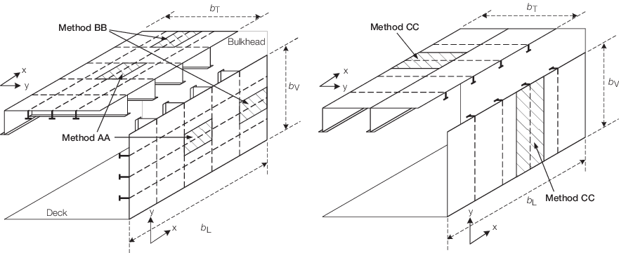
3.3.5 The
stresses in the plating of a primary/secondary plating system are
to be derived using the recommended equations and stiffener end conditions
given in Table 3.3.2 Stress determination in
longitudinal plating of primary/secondary systems, e.g., decks and longitudinal
bulkheads and Table 3.3.3 Stress determination in transverse
plating of primary/secondary systems, e.g., transverse bulkheads The stresses in the flanges
of panel stiffeners are given in Vol 1, Pt 7, Ch 3, 2.3 Stresses in secondary and primary member stiffeners 2.3.6 using
the conditions given in Vol 1, Pt 7, Ch 3, 3.2 Stress determination in primary members 3.2.3 and Vol 1, Pt 7, Ch 3, 3.3 Stress determination in primary/secondary systems 3.3.3 The stresses and nomenclature
are shown in Figure 3.3.1 Definition of stresses in a primary/secondary stiffened panel
Table 3.3.2 Stress determination in
longitudinal plating of primary/secondary systems, e.g., decks and longitudinal
bulkheads
| Stress direction
|
Stress equation
|
Stiffener end condition
|
| Plating
|
Stiffener flange
|
|
Method AA Longitudinal secondary stiffeners
|
| σx
|
Equation A
σx = σxg + σxb
N/mm2
|
σsx,
see
Vol 1, Pt 7, Ch 3, 3.11 Derivation of total stresses in stiffener flanges
|
Built in
|
| σy
|
Equation D
σy = σyg N/mm2
|
N.A.
|
N.A.
|
| τxy
|
Equation E

|
δs,
see
Vol 1, Pt 7, Ch 3, 2.3 Stresses in secondary and primary member stiffeners 2.3.4
τs, see
Vol 1, Pt 7, Ch 3, 2.3 Stresses in secondary and primary member stiffeners 2.3.5
|
|
|
Method BB Longitudinal secondary stiffeners adjacent to bulkhead
|
| σx
|
Equation A
σx = σxg + σxb
N/mm2
|
|
Edge end built in.
Other end free to deflect,no rotation, see Note 2
|
| σy
|
Equation D
σy = σyg N/mm2
|
N.A.
|
N.A.
|
| τxy
|
Equation E

|
δs,
see
Vol 1, Pt 7, Ch 3, 2.3 Stresses in secondary and primary member stiffeners 2.3.4
τs, see
Vol 1, Pt 7, Ch 3, 2.3 Stresses in secondary and primary member stiffeners 2.3.5
|
|
|
Method CC Transverse secondary stiffeners
|
| σx
|
Equation B
σx = σxg N/mm2
|
N.A.
|
N.A.
|
| σy
|
Equation C
σy = σyg +
σybN/mm2
|
σsx, see
Vol 1, Pt 7, Ch 3, 3.11 Derivation of total stresses in stiffener flanges
|
Built
in
|
| τxy
|
Equation E

|
δs, see
Vol 1, Pt 7, Ch 3, 2.3 Stresses in secondary and primary member stiffeners 2.3.4
τs, see
Vol 1, Pt 7, Ch 3, 2.3 Stresses in secondary and primary member stiffeners 2.3.5
|
|
Note
2. Alternatively the deflection from the
transverse member over its full span, excluding the support from
longitudinal stiffeners, may be applied.
|
|
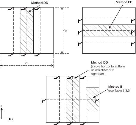
Table 3.3.3 Stress determination in transverse
plating of primary/secondary systems, e.g., transverse bulkheads
| Stress direction
|
Stress equation
|
Stiffener end condition
|
| Plating
|
Stiffener flange
|
|
Method DD Vertical secondary stiffeners
|
| σx
|
Equation H
σx = σxg + σxb
N/mm2
|
σsx,
see
Vol 1, Pt 7, Ch 3, 3.11 Derivation of total stresses in stiffener flanges
|
N.A.
|
| σy
|
Equation G
σy = σyg N/mm2
|
N.A.
|
Built in
|
| τxy
|
Equation J

|
δs,
see
Vol 1, Pt 7, Ch 3, 2.3 Stresses in secondary and primary member stiffeners 2.3.4
τs, see
Vol 1, Pt 7, Ch 3, 2.3 Stresses in secondary and primary member stiffeners 2.3.5
|
|
|
Method EE Horizontal secondary stiffeners
|
| σx
|
Equation I
σx = σxv N/mm2
|
N.A.
|
N.A.
|
| σy
|
Equation F
σy = σyg + σyb
N/mm2
|
σsx,
see
Vol 1, Pt 7, Ch 3, 3.11 Derivation of total stresses in stiffener flanges
|
Built in
|
| τxy
|
Equation J

|
δs,
see
Vol 1, Pt 7, Ch 3, 2.3 Stresses in secondary and primary member stiffeners 2.3.4
τs, see
Vol 1, Pt 7, Ch 3, 2.3 Stresses in secondary and primary member stiffeners 2.3.5
|
|
|
|
|
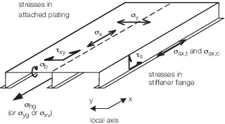
Figure 3.3.1 Definition of stresses in a primary/secondary stiffened panel
3.3.6 When
it is considered that a different combination of stresses is likely
to produce higher stresses, then this combination should be considered.
3.4 Stress determination in grillage systems
3.4.1 A grillage
system of plating and stiffeners is one where the bending stiffness
of the orthogonal stiffeners are similar in magnitude and the orthogonal
stiffeners work together to support the applied loads. The grillage
system is in turn supported by primary structural items such as deep
girders, deep transverse beams or bulkheads.
3.4.2 An example
of a grillage system is as follows: plating supported by a longitudinal
spacing of 600 mm and a transverse spacing of 1500 mm with the transverse
stiffeners having an section inertia value of 1,5 times the longitudinal
stiffeners.
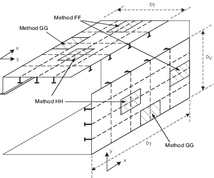
3.4.3 Normally
it is necessary to use direct calculations to evaluate the stresses
within a grillage plating system. However, it may be sufficient to
consider the stiffeners perpendicular to an edge of the grillage panel
as acting independently of the grillage system. See
Table 3.3.4 Stress determination in
longitudinal plating of grillage systems, e.g., decks and longitudinal
bulkheads and Methods FF and GG
in the attached figure, also Methods II and JJ in Table 3.3.5 Stress determination in transverse
plating of grillage systems, e.g., transverse bulkheads..
Table 3.3.4 Stress determination in
longitudinal plating of grillage systems, e.g., decks and longitudinal
bulkheads
| Stress direction
|
Stress equation
|
Stiffener end condition
|
| Plating
|
Stiffener flange
|
|
Method FF At the fore and aft edges of a grillage panel
|
| σx
|
Equation A
σx = σxg + σxb
N/mm2
|
σsx,
see
Vol 1, Pt 7, Ch 3, 3.1 General 3.1.1
|
Edge end built
in. Other end free to deflect, no rotation, see Note 2
|
| σy
|
Equation D
σy = σyg N/mm2
|
N.A.
|
N.A.
|
| τxy
|
Equation E

|
δs,
see
Vol 1, Pt 7, Ch 3, 2.3 Stresses in secondary and primary member stiffeners 2.3.4
τs, see
Vol 1, Pt 7, Ch 3, 2.3 Stresses in secondary and primary member stiffeners 2.3.5
|
|
|
Method GG At the port and starboard edges of a grillage panel
|
| σx
|
Equation B
σx = σxg N/mm2
|
N.A.
|
N.A.
|
| σy
|
Equation C
σy = σyg + σyb
N/mm2
|
σsx,
see
Vol 1, Pt 7, Ch 3, 3.11 Derivation of total stresses in stiffener flanges
|
Edge end built in.
Other end free to deflect, no rotation, see Note 3
|
| τxy
|
Equation E

|
δs,
see
Vol 1, Pt 7, Ch 3, 2.3 Stresses in secondary and primary member stiffeners 2.3.4
τs, see
Vol 1, Pt 7, Ch 3, 2.3 Stresses in secondary and primary member stiffeners 2.3.5
|
|
|
Method HH At the centre of a grillage panel
|
| σx
|
Equation A
σx = σxg + σxb
N/mm2
|
σsx,
see
Vol 1, Pt 7, Ch 3, 3.11 Derivation of total stresses in stiffener flanges
|
Built in
|
| σy
|
Equation C
σy = σyg +
σybN/mm2
|
σsx,
see
Vol 1, Pt 7, Ch 3, 3.11 Derivation of total stresses in stiffener flanges
|
Built in
|
| τxy
|
Equation E

|
δs,
see
Vol 1, Pt 7, Ch 3, 2.3 Stresses in secondary and primary member stiffeners 2.3.4
τs, see
Vol 1, Pt 7, Ch 3, 2.3 Stresses in secondary and primary member stiffeners 2.3.5
|
|
Note
2. Alternatively the deflection from the
longitudinal member over its full span, excluding the support from
transverse stiffeners, may be applied.
Note
3. Alternatively the deflection from the
transverse member over its full span, excluding the support from
longitudinal stiffeners, may be applied.
|
|
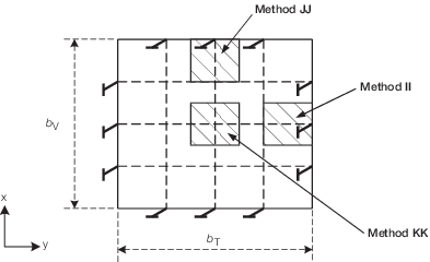
Table 3.3.5 Stress determination in transverse
plating of grillage systems, e.g., transverse bulkheads.
| Stress direction
|
Stress equation
|
Stiffener end condition
|
| Plating
|
Stiffener flange
|
|
Method II Horizontal stiffeners at the port and starboard edges of a
grillage panel
|
| σx
|
Equation I
σx = σxv N/mm2
|
N.A.
|
Edge end Built
in.
Other end free to deflect, no rotation, see Note
2
|
| σy
|
Equation F
σy = σyg + σyb
N/mm2
|
σsx,
see
Vol 1, Pt 7, Ch 3, 3.11 Derivation of total stresses in stiffener flanges
|
N.A.
|
| τxy
|
Equation J

|
δs,
see
Vol 1, Pt 7, Ch 3, 2.3 Stresses in secondary and primary member stiffeners 2.3.4
τs, see
Vol 1, Pt 7, Ch 3, 2.3 Stresses in secondary and primary member stiffeners 2.3.5
|
—
|
|
Method JJ Vertical stiffeners at the top and bottom edges of a
grillage panel
|
| σx
|
Equation H
σx = σxv + σxb
N/mm2
|
σsx,
see
Vol 1, Pt 7, Ch 3, 3.11 Derivation of total stresses in stiffener flanges
|
N.A.
|
| σy
|
Equation G
σy = σyg N/mm2
|
N.A.
|
Edge end built in.
Other end free to deflect, no rotation, see Note 3
|
| τxy
|
Equation J

|
δs,
see
Vol 1, Pt 7, Ch 3, 2.3 Stresses in secondary and primary member stiffeners 2.3.4
τs
see
Vol 1, Pt 7, Ch 3, 2.3 Stresses in secondary and primary member stiffeners 2.3.5
|
—
|
|
Method KK At the centre of a grillage panel
|
| σx
|
Equation H
σx = σxv + σxb
N/mm2
|
σsx,
see
Vol 1, Pt 7, Ch 3, 3.11 Derivation of total stresses in stiffener flanges
|
Built in
|
| σy
|
Equation F
σy = σyg + σyf +
σyb N/mm2
|
σsx,
see
Vol 1, Pt 7, Ch 3, 3.11 Derivation of total stresses in stiffener flanges
|
Built in
|
| τxy
|
Equation J

|
δs,
see
Vol 1, Pt 7, Ch 3, 2.3 Stresses in secondary and primary member stiffeners 2.3.4
τs, see
Vol 1, Pt 7, Ch 3, 2.3 Stresses in secondary and primary member stiffeners 2.3.5
|
—
|
Note
2. Alternatively the deflection of the
vertical member over its full span, excluding the support from
horizontal stiffeners, may be applied instead of the free to deflect
condition.
Note
3. Alternatively the deflection from the
horizontal member over its full span, excluding the support from
vertical stiffeners, may be applied instead of the free to deflect
condition.
|
|
3.4.4 The
bending stresses in the edge stiffeners may be evaluated on the basis
of encastre at the edge of the grillage panel and no rotation and
free to deflect at the intersection with the first orthogonal stiffener.
3.4.5 In this
case, the total stress analysis is to be based on the membrane stress
in the plating of the grillage panel and consider the bending stresses
in the middle stiffener perpendicular to the edge of the panel.
3.4.6 It will
be necessary to derive the total stress at the edge of the panel for
each stiffener direction.
3.4.7 The
total stress in the centre of the grillage panel should also be checked.
In this case it is necessary to consider the stresses in the plate
due to bending of the stiffener in each direction as well as the plating
stresses due to membrane loads.
3.4.8 The
stresses in the plating of a grillage plating system are to be derived
using the recommended equations and stiffener end conditions given
in Table 3.3.4 Stress determination in
longitudinal plating of grillage systems, e.g., decks and longitudinal
bulkheads and Vol 1, Pt 7, Ch 3, 3.3 Stress determination in primary/secondary systems 3.3.5 The stresses in the flanges
of the panel stiffener are given by Vol 1, Pt 7, Ch 3, 2.3 Stresses in secondary and primary member stiffeners 2.3.6, using the conditions given in Table 3.3.4 Stress determination in
longitudinal plating of grillage systems, e.g., decks and longitudinal
bulkheads and Table 3.3.5 Stress determination in transverse
plating of grillage systems, e.g., transverse bulkheads.. The
stresses are illustrated in Figure 3.3.2 Definition of stresses in a grillage stiffened panel
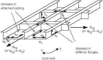
Figure 3.3.2 Definition of stresses in a grillage stiffened panel
3.4.9 When
it is considered that a different combination of stresses is likely
to produce higher stresses, then this combination should be considered.
3.5 Derivation of the combined longitudinal stress on panels subjected
to hull girder bending
3.5.2
Equation
A is used for grillage systems or plating systems with the
secondary stiffeners orientated in the longitudinal direction. For
these systems, the stress in the plating/stiffener combination due
to local bending needs to be considered in addition to the membrane
stresses due to hull girder bending. The stress components in Equation
A are given below.
3.5.3
Equation
B is used for plating systems with the secondary stiffeners
orientated in the transverse (or vertical) direction. For these systems
only the longitudinal stress due to hull girder bending needs to be
considered.
3.5.4 The
longitudinal stress components associated with Equations A and B are
given below:
|
σxg
|
= |
is
the longitudinal membrane stress due to hull girder bending |
|
σxb
|
= |
is
the stress in the plating due to bending of the longitudinal stiffener/plate
combination under lateral pressure loading or lateral inertial loads
Normally σxb is to be taken as the negative
value of σsp, i.e. σsp,c, when the hull
girder bending stress σxg is negative, similarly the
positive value of σsp, i.e. σsp,t, is
to be taken when σxg is positive, see
Figure 3.2.2 Bending stresses in stiffener beam However, there may be
cases where it is necessary to consider the opposite situation
When
appropriate, the σxb value is to be the summation of
stresses as result of inertial pressures and inertial point loads
|
|
z
na
|
= |
vertical distance above the neutral axis of the structural member
under consideration, in metres |
3.6 Derivation of the combined transverse stress acting on panels
subjected to hull girder bending
3.6.2
Equation
C is used for grillage systems or plating systems with the
secondary stiffeners orientated in the transverse direction. For these
systems, the stress in the plating/stiffener combination due to local
bending needs to be considered in addition to membrane stresses due
to global transverse loading. The stress components in Equation C
are given below.
3.6.3
Equation
D is used for plating systems with the secondary stiffeners
orientated in the longitudinal direction. For these systems, only
membrane stress due to global transverse loading needs to be considered.
3.6.4 The
transverse stress components associated with equations C and D are
given below:
|
σyg
|
= |
is
the membrane stress due to global transverse loading |
|
σyb
|
= |
is
the stress in the plating due to bending of the longitudinal stiffener/plate
combination under lateral pressure loading or lateral inertial loads
Normally, σyb is to be taken as the negative
value of σsp, i.e. σsp,c, when the global
transverse stress σyg is negative, similarly the positive
value of σsp, i.e. σsp,t, is to be taken
when σyg is positive, see
Figure 3.3.2 Definition of stresses in a grillage stiffened panel. However, there may be
cases where it is necessary to consider the opposite situation.
When appropriate, the σyb value is to be the
summation of stresses as result of inertial pressures and inertial
point loads
|
|
t
p
|
= |
thickness of plating, in mm |
|
b
L
|
= |
breadth of plating, in metres, over which the load LT applies.
Normally, this is the distance between decks or the height of the
plating panel.
|
3.7 Derivation of the total shear stress
3.7.1
Equation
E is used to derive the total shear stress in the plating for
all plating systems.
3.7.2 The
shear stress components associated with Equation E are given below:
|
|Q| |
= |
denotes the absolute value of
parameter Q
|
 hg
hg
|
= |

|
|
Q
D
|
= |
is global hull girder shear force, in kN. This will be zero
for all transverse plating systems |
A
z,  hg and δi are given in Vol 1, Pt 6, Ch 4, 2.3 Shear strength 2.3.6
NOTE
All shear force loads are to be
assumed positive.
3.8 Derivation of the combined transverse stress acting on transversely
orientated panels
3.8.2
Equation
F is used for grillage systems or plating systems with the
secondary stiffeners orientated in the transverse direction.
3.8.3
Equation
G is used for plating systems with the secondary stiffeners
orientated in the vertical direction.
3.9 Derivation of the combined vertical stress acting on transversely
orientated panels
3.9.2
Equation
H is used for grillage systems or plating systems with the
transverse secondary stiffeners orientated in the vertical direction.
3.9.3
Equation
I is used for plating systems with the secondary stiffeners
orientated in the transverse direction.
3.9.4 The
vertical stress components associated with Equations H and I are given
below:
|
σxv
|
= |
is
the membrane stress due to vertical loading |
|
|
= |
 N/mm2 N/mm2
|
|
σxb
|
= |
is
the stress in the plating due to bending of the longitudinal stiffener/plate
combination under lateral pressure loading or lateral inertial loads
Normally σxb is to be taken as the negative
value of σsp, i.e. σsp,c, when the vertical
stress σxv is negative, similarly the positive value
of σsp, i.e. σsp,t, is to be taken when
σxv is positive, see
Vol 1, Pt 7, Ch 3, 3.2 Stress determination in primary members 3.2.2. However, there may be cases
where it is necessary to consider the opposite situation
When
appropriate, the σxb value is to be the summation of
stresses as result of inertial pressures and inertial point loads
|
where
|
t
p
|
= |
thickness of plating, in mm |
|
b
T
|
= |
breadth of plating, in metres, over which the load LV applies.
Normally, this is the distance between the side shell(s) or longitudinal
bulkheads but it is to be reduced for the presence of large openings.
|
3.10 Derivation of the total shear stress on transversely orientated
panels
3.10.1
Equation
J is used to derive the total shear stress in any plating system
which is not subjected to global hull girder shear force.
3.10.2 The
shear stress components associated with Equation J are given below:
NOTE
All shear force loads are to be
assumed positive.
3.11 Derivation of total stresses in stiffener flanges
3.11.1 The
total compressive and tensile stresses in stiffener flanges, σsx, are given by the following:
|
σsx,c
|
= |
σax + σsf,c N/mm2 (compressive)
|
|
σ
sx,t
|
= |
σax + σsf,t N/mm2 (tensile)
|
where
|
σax
|
= |
is the axial stress
in the stiffener at the combined stiffener plate neutral axis, this
is normally to be taken as the membrane stress in the plating, i.e.
σxg, σyg or σxv depending
on the orientation of the stiffener, see
Vol 1, Pt 7, Ch 3, 3.5 Derivation of the combined longitudinal stress on panels subjected to hull girder bending 3.5.4, Vol 1, Pt 7, Ch 3, 3.6 Derivation of the combined transverse stress acting on panels subjected to hull girder bending
3.6.4 or Vol 1, Pt 7, Ch 3, 3.9 Derivation of the combined vertical stress acting on transversely orientated panels 3.9.4
|
|
σsf,t, σsf,c
|
= |
are the tensile and compressive bending stresses the stiffener
flange, see
Vol 1, Pt 7, Ch 3, 2.3 Stresses in secondary and primary member stiffeners 2.3.3 and Vol 1, Pt 7, Ch 3, 2.3 Stresses in secondary and primary member stiffeners 2.3.6, using the appropriate boundary
conditions given in Vol 1, Pt 7, Ch 3, 3 Stress analysis model
|
3.11.2 These
formulae may be applied to grillage and primary/secondary stiffened
plating systems. The stresses in a stiffener beam subjected to more
than one load may be derived by adding the stresses from each load
component.
3.12 Derivation of total equivalent stress
3.12.1 The
total equivalent stress or von Mises stress, σvm, is
to be derived using the following formula:
|