In applying the Articles and Regulations of the 1966 Load
Line Convention, the following interpretations are recommended to
Contracting Governments in order to ensure the uniform application
of the relevant Articles and Regulations.
A ship which is composed of a series of permanently attached
sections should have a freeboard determined by the overall length
of the series. A rigidly attached, but detachable, propulsion section
should be included in the total length (L). A non-rigidly
attached, detachable propulsion section should be treated as a separate
ship.
(IACS interpretation LL.1)
Even where an increase in draught is only of the order of
25 mm or 50 mm there should be no relaxation from the condition that
existing ships comply with all the requirements.
An exemption certificate according to article
6 should be granted by the Administration for ships whose operational
features lead to submergence of the load line mark during loading
or unloading, to avoid contravention of article
12(1).
(IACS interpretation LL.19)
The model form of certificates given in Annex III of the
Load Line Convention should be strictly adhered to and any deviations
from this pattern should be avoided.
(IACS interpretation LL.51)
Where freeboards are not required to be increased, because
of such considerations as strength (regulation
1), location of shell doors (regulation
21) or sidescuttles (regulation 23)
or other reasons, then:
on the actual freeboard deck may be a required for a superstructure
deck, provided the summer freeboard is such that the resulting draught
will not be greater than that corresponding to the minimum freeboard
calculated from an assumed freeboard deck situated at a distance equal
to a standard super-structure height below the actual freeboard deck.
Similar considerations may be given in cases of draught limitation
on account of bow height (regulation 39).
Discontinuous freeboard deck, stepped freeboard deck
(IACS interpretation LL.48/Rev.1)
1 Where a step exists in the freeboard deck, creating
a discontinuity extending over the full breadth of the ship, and this
step is in excess of 1 m in length, regulation
3(9) should apply (figure 1).
A step 1 m or less in length should be treated as a recess in accordance
with paragraph 2.
2 Where a recess is arranged in the freeboard
deck, and this recess does not extend to the side of the ship, the
freeboard calculated without regard to the recess is to be corrected
for the consequent loss of buoyancy. The correction should be equal
to the value obtained by dividing the volume of the recess by the
waterplane area of the ship (A
w) at 85% of
the least moulded depth (figure 2).
-
.1 The correction should be a straight addition
to the freeboard obtained after all other corrections have been applied,
except bow height correction.
-
.2 Where the freeboard, corrected for lost buoyancy
as above, is greater than the minimum geometric freeboard determined
on the basis of a moulded depth measured to the bottom of the recess,
the latter value may be used.
3 Recesses in a second deck, designated as the
freeboard deck, may be disregarded in this interpretation provided
all openings in the weather deck are fitted with weathertight closing
appliances.
4 Due regard is to be given to the drainage of
exposed recesses and to free surface effects on stability.
5 This interpretation is not intended to apply
to dredgers, hopper barges or other similar types of ships with large
open holds, where each case should require individual consideration.
(IACS interpretation LL.2)
The correction for thickness of sheathing on the exposed
freeboard deck,  is applicable only when the deck is completely sheathed
between super-structures. In other cases the correction should be
is applicable only when the deck is completely sheathed
between super-structures. In other cases the correction should be  where l = length of sheathed area which extends
from side to side. Only wood sheathing should be considered.
where l = length of sheathed area which extends
from side to side. Only wood sheathing should be considered.
(IACS interpretation LL.39)
When a lower deck is designated as the freeboard deck, it
should be continuous in fore and aft direction as well as athwartship.
Such freeboard deck as minimum should consist of suitably framed stringers
at the ship sides and transversely at each watertight bulkhead which
extends to the upper deck, within cargo spaces. The width of these
stringers should not be less than can be conveniently fitted having
regard to the structure and the operation of the ship. Any arrangement
of stringers should be such that structural requirement can also be
met.
Position of freeboard deck on float on/float off barge
carriers (Regulation 3(9))
(IACS interpretation LL.68)
Float on/float off barge carriers are designed to be ballasted
such that the bottom of their cargo space(s) (well deck) submerges
below the waterline to allow barges being floated in and out.
If such a ship is fitted with weathertight closures for
the cargo space(s) and a watertight enclosure at the stern, the uppermost
complete deck may be taken as the freeboard deck.
If such a ship is not fitted with weathertight closures
for the cargo space(s) or a watertight enclosure at the stern, the
well deck should be taken as the freeboard deck, while buoyant spaces
above may be considered as superstructures in accordance with the
provisions of the interpretation relating to regulation
34(1) of the Convention referred to in section 1 or regulation
34(1) of the 1988 Protocol.
If such a ship is not fitted with weathertight closures
for the cargo space(s) but has a watertight enclosure at the stern,
the uppermost complete deck may be taken as the freeboard deck provided
that:
-
.1 the structure of the freeboard deck complies
with the provisions of the interpretation relating to regulation 3(9) of the Convention referred
to in circular LL.3/Circ.77;
-
.2 the calculated freeboard is corrected for any
missing buoyancy above the well deck in accordance with the provisions
of the interpretation relating to regulations
3(5)(c) and 3(9) of the Convention referred to in circular
LL.3/Circ.69; and
-
.3 a satisfactory safety level at the resulting
draught is demonstrated according to alternative concepts.
(IACS interpretation LL.3)
A bridge or poop should not be regarded as enclosed unless
access is provided for the crew starting from any point on the uppermost
complete exposed deck or higher to reach machinery and other working
spaces inside these superstructures by alternative means which are
available at all times when bulkhead openings are closed.
(IACS interpretation LL.4)
"Permanently marked" is considered to include welding of
the marks on the sides of the ship provided the usual precautions
as to material, electrodes etc. are observed.
(IACS interpretation LL.5)
Doors should generally open outwards to provide additional
security against the impact of the sea. Doors which open inwards should
be exceptionally approved.
Portable sills should be avoided. However, in order to facilitate
the loading/unloading of heavy or bulky spare parts, portable sills
may be fitted on the following conditions:
Whenever the sills are replaced after removal, the weathertightness
of the sills and related doors should be verified by hose testing.
The dates of removal, replacing and hose testing should be recorded
in the ship's log-book.
(IACS interpretation LL.20)
To avoid stresses and deflections exceeding those given
in the above Regulations along construction elements of variable cross-section,
the required section modulus calculated as for construction elements
of constant cross-section should be increased by a factor K expressed
by:
where α = l
1/l
0, γ = W1/W0
The value
of factor K obtained by the formula should be not less than unity.
l
1, l
0, W1 and
W0 are indicated in the figure
3 below:
The moment of inertia should likewise be increased by the
factor C expressed by:
where α = l
1/l
0, β = I1/I0
The value
of factor C obtained by the formula should be not less
than unity.
I1 and I0 are indicated
in figure 3 above.
The use of the above formulae should be limited to the determination
of the strength of hatch beams and covers in which abrupt changes
in the section of the face material do not occur along the length
of the beam or cover.
(IACS interpretation LL.40/Rev.1)
This interpretation is not intended to be applied to existing
ships.
Acceptable equivalent means to steel bars should consist
of devices and materials which could provide strength equivalent to,
and elasticity not greater than that of, steel.
Steel wire ropes should not be regarded as satisfactory
equivalent means.
Care should be taken to ensure that tarpaulins are adequately
protected from the possibility of damage arising from the use of securing
devices which do not provide a flat bearing surface.
Hatchways closed by weathertight covers of steel or
other equivalent material fitted with gaskets and clamping devices
(Regulations 16 and
27(7)(c))
(IACS interpretation LL.6)
Where hatchways are fitted with coamings of standard height,
no extra strengthening (beyond what is required in the Load Line Convention)
should be required for covers loaded with cargo, even dense cargo,
provided the load does not exceed 1.75 tonnes/m2 (in position
1).
No extra strengthening is recommended for hatchway covers
on vessels which are assigned freeboards less than those based on
Table B, except for flush hatchway covers which are fitted on the
freeboard deck forward of the quarter length, in which case the section
modulus and the moment of inertia should be increased 15% over that
required by regulation 16.
(IACS interpretation LL.7)
Where casings are not protected by other structures, double
doors should be required for type A or type B ships assigned freeboards
less than those based on table Bfootnote. An
inner sill of 230 mm in conjunction with the outer sill of 600 mm
is recommended.
Machinery space and emergency generator room ventilator
coaming heights (Regulations 17(2), 19(3) and 19(4))
(IACS interpretation LL.58)
Regulation 17(2) requires that the coamings of machinery
space ventilators situated in exposed positions on the freeboard and
superstructure decks shall be as high above the deck as is reasonable
and practicable.
In general, ventilators necessary to continuously supply
the machinery space and, on demand, immediately supply the emergency
generator room should have coamings which comply with regulation 19(3), without having to fit
weathertight closing appliances.
However, where due to ship size and arrangement this is
not practicable, lesser heights for machinery space and emergency
generator room ventilator coamings may be accepted with the provision
of weathertight closing appliances in accordance with regulation 19(4)
in combination with other suitable arrangements to ensure an uninterrupted,
adequate supply of ventilation to these spaces.
Only those doorways in deckhouses leading to or giving access
to companionways leading below, need to be fitted with doors in accordance
with regulation 12.
Alternatively, if stairways within a deckhouse are enclosed
within properly constructed companionways fitted with doors complying
with regulation 12, then the external
doors need not be weathertight.
Where an opening exists in a superstructure deck or in the
top of a deckhouse on the freeboard deck which gives access to space
below the freeboard deck or to a space within an enclosed superstructure
and is protected by a deckhouse, then it is considered that only those
side scuttles fitted in spaces which give direct access to an open
stairway need be fitted with deadlights in accordance with regulation 23. A cabin is considered to
provide adequate protection against the minimal amount of water which
will enter through a broken side scuttle glass fitted on the second
tier.
.1 where access is provided from the deck above
as an alternative to access from the freeboard deck in accordance
with regulation 3(10)(b) then the
height of sills into a bridge or poop should be 380 mm. The same consideration
should apply to deckhouses on the freeboard deck;
.2 where access is not provided from above, the
height of the sills to doorways in a poop bridge or deckhouse on the
freeboard deck should be 600 mm;
.3 where the closing appliances of access openings
in superstructures and deckhouses are not in accordance with regulation 12, interior deck openings are
to be considered exposed, i.e. situated in the open deck.
Protection of openings in raised quarter-decks (Regulations 18(2) and 23)
(IACS interpretation LL.46.Rev.2)
By extension of regulation 23 and
the interpretation of regulation 18(2) and
(3) regarding miscellaneous openings in freeboard and superstructure
decks, referred to above (see previous unified interpretation), deckhouses
situated on a raised quarter-deck or on a superstructure of less than
standard height may be treated as being on the second tier as far
as the provision of deadlights and sidescuttles and windows is concerned,
provided that the height of the raised quarter-deck or superstructure
on which they are situated is equal to, or greater than, the standard
quarter-deck height.
Regarding the requirement to protect openings in superstructures
(regulation 18(2)), it is considered
that openings in the top of a deckhouse on a raised quarter-deck or
superstructure of less than standard height having a height equal
to, or greater than, the standard quarter-deck height should be provided
with an acceptable means of closing but need not be protected by an
efficient deckhouse or companionway as defined in the regulation provided
that the height of the deckhouse is at least the height of superstructure.
Minimum wall thickness of pipes (Regulations 19, 20 and 22)
(IACS interpretation LL.36/Rev.1)
For pipes covered by the above regulations the following
minimum wall thicknesses are recommended for those Administrations
which do not have national regulations:
1 Scupper and discharge pipes, where substantial
thickness is not required, and venting pipes other than specified
in 3 below:
-
.1 For pipes having external diameter equal to
or less than 155 mm thickness should not be less than 4.5 mm;
-
.2 For pipes having external diameter equal to
or more than 230 mm thickness should not be less than 6 mm.
Intermediate sizes should be determined by linear interpolation.
2 Scupper and discharge pipes where substantial
thickness is required:
-
.1 For pipes having external diameter equal to
or less than 80 mm thickness should not be less than 7 mm;
-
.2 For pipes having external diameter of 180 mm
thickness should not be less than 10 mm;
-
.3 For pipes having external diameter equal to
or more than 220 mm thickness should not be less than 12.5 mm.
Intermediate sizes should be determined by linear interpolation.
3 Venting pipes in position 1 and 2 leading to
spaces below the freeboard deck or to spaces within closed superstructures:
-
.1 For pipes having external diameter equal to
or less than 80 mm thickness should not be less than 6 mm;
-
.2 For pipes having external diameter equal to
or more than 165 mm thickness should not be less than 8.5 mm.
Intermediate sizes should be determined by linear interpolation.
(IACS interpretation LL.52)
Where required by regulation 19,
weathertight closing appliances for all ventilators in positions 1
and 2 are to be of steel or other equivalent materials.
Wood plugs and canvas covers are not acceptable in these
positions.
(IACS interpretation LL.10)
For ships assigned timber freeboards the air pipes should
be provided with automatic closing appliances.
In cases where air pipes are led through the side of superstructures,
it is recommended that the height of their openings be more than 2.3
m above the summer load waterline.
(IACS interpretation LL.49)
This interpretation is not intended to be applied to existing
ships.
The means of closing air pipes should be weathertight and
of an automatic type if the openings of the air pipes to which the
devices are fitted would be submerged at an angle of less than 40°
(or any lesser angle which may be needed to suit stability requirements)
when the ship is floating at its summer load line draught. Pressure
vacuum valves (P.V. valves) may be accepted on tankers.
Wooden plugs and trailing canvas hoses should not be accepted
as closing devices for air pipes in positions 1 and 2.
Special requirements for vehicle ferries, ro-ro ships
and other ships of similar type (Regulation
21)
(IACS interpretation LL.32)
Stern, bow and side doors of large dimensions, when manual
devices would not be readily accessible, should be normally secured
by means of power systems. Alternative means of securing should also
be provided for emergency use in case of failure of the power systems.
In a ship in which the lower deck has been designated as
the freeboard deck, the means of closing openings in the shell plating
below the weather deck but above the freeboard deck should be so designed
as to ensure integrity against the sea commensurate with the surrounding
shell plating, having regard to the position of the opening in relation
to the water-line. In such a ship the following principles apply:
-
.1 the effectiveness of closing appliances fitted
at cargo ports and other similar openings in the shell of a ship depends
on regular observations and maintenance;
-
.2 hose tests are a practical means of verifying
the weathertightness or watertightness of such closing appliances;
and
-
.3 consideration should be given to the fitting
of alarms giving warning of leakage in way of doors in exposed positions.
Cargo ports or similar openings below the uppermost
load line (Regulation 21(2))
(IACS interpretation LL.21)
Cargo ports or similar openings may be submerged provided
the safety of the ship is in no way impaired. It is considered that
the fitting of a second door of equivalent strength and watertightness
is an acceptable arrangement. In this case a leakage detection device
should be provided in the compartment between the two doors. Further,
drainage of this compartment to the bilges controlled by an easily
accessible screw down valve, should be arranged. The outer door should
preferably open outwards.
(IACS interpretation LL.11)
An acceptable equivalent to one automatic non-return valve
with a positive means of closing from a position above the freeboard
deck would be one automatic non-return valve and one sluice valve
controlled from above the freeboard deck. Where two automatic non-return
valves are required, the inboard valve should always be accessible
under service conditions, i.e. the inboard valve should be above the
level of the tropical load waterline. If this is not practicable,
then, provided a locally controlled sluice valve is interposed between
the two automatic non-return valves, the inboard valve need not be
fitted above the load waterline.
Where sanitary discharges and scuppers lead overboard through
the shell in way of manned machinery spaces, the fitting to shell
of a locally operated position closing valve together with a non-return
valve inboard, is considered to provide protection equivalent to the
requirements of regulation 22(1).
The requirements of regulation
22(1) for non-return valves should be applicable only to those
discharges which remain open during the normal operation of a ship.
For discharges which must necessarily be closed at sea, such as gravity
drains from topside ballast tanks, a single screw-down valve operated
from the deck is considered to provide efficient protection.
Position of the inboard end of discharges when a timber
freeboard is assigned (Regulation 22(1))
(IACS interpretation LL.22)
The position of the inboard end of discharges should be
related to the timber summer load waterline when a timber freeboard
is assigned.
(IACS interpretation LL.12)
For those ships where the freeboard is reduced on account
of subdivision characteristics, side scuttles fitted outside the space
considered flooded and which are below the final water-line should
be of the non-opening type.
(IACS interpretation LL.62)
Sidescuttles and windows together with their glasses, deadlightsfootnote and storm coversfootnote, if fitted,
should be of approved design and substantial construction in accordance
with, or equivalent to, recognized national or international standards.
Non-metallic frames should not be acceptable.
Sidescuttles are defined as being round or oval openings
with an area not exceeding 0.16 m2. Round or oval openings
having areas exceeding 0.16 m2 should be treated as windows.
Windows are defined as being rectangular openings generally,
having a radius at each corner relative to the window size in accordance
with recognized national or international standards, and round or
oval openings with an area exceeding 0.16 m2.
Sidescuttles to the following spaces should be fitted with
efficient hinged inside deadlights:
-
.1 spaces below freeboard deck;
-
.2 spaces within the first tier of enclosed superstructures;
and
-
.3 first tier deckhouses on the freeboard deck
protecting openings leading below or considered buoyant in stability
calculations.
The deadlights should be capable of being effectively closed
and secured watertight, if fitted below freeboard deck, and weathertight,
if fitted above.
Sidescuttles should not be fitted in such a position that
their sills are below a line drawn parallel to the freeboard deck
at side and having its lowest point 2.5% of the breadth B,
or 500 mm, whichever is the greatest distance, above the summer load
line (or timber summer load line, if assigned).
Sidescuttles should be of the non-opening type in ships
subject to damage stability regulations, if calculations indicate
that they would become immersed by any intermediate stage of flooding
or the final equilibrium waterplane in any required damage case.
Windows should not be fitted below the freeboard deck, in
the first tier end bulkheads or sides of enclosed superstructures
and in first tier deckhouses considered buoyant in the stability calculations
or protecting openings leading below.
Sidescuttles and windows at the side shell in the second
tier, protecting direct access below or considered buoyant in the
stability calculations, should be provided with efficient hinged inside
deadlights capable of being effectively closed and secured weathertight.
Sidescuttles and windows set inboard from the side shell
in the second tier, protecting direct access below to spaces listed
in paragraph 3.4 above, should be provided with either efficient hinged
inside deadlights or, where they are accessible, permanently attached
external storm covers of approved design and of substantial construction
and capable of being effectively closed and secured weathertight.
Cabin bulkheads and doors in the second tier separating
sidescuttles and windows from a direct access leading below may be
accepted in place of deadlights or storm covers fitted to the sidescuttles
and windows.
Deckhouses situated on a raised quarter-deck or on the deck
of a superstructure of less than standard height may be regarded as
being in the second tier as far as the provision of deadlights is
concerned, provided the height of the raised quarter-deck or superstructure
is equal to, or greater than, the standard quarter-deck height.
Fixed or opening skylights should have glass thickness appropriate
to their size and position as required for sidescuttles and windows.
Skylights glasses in any position should be protected from mechanical
damage and, where fitted in position 1 or 2, should be provided with
robust deadlights or storm covers permanently attached.
(IACS interpretation LL.60)
In the case of ships having open superstructures on the
freeboard or superstructure decks, which open to wells formed by bulwarks
on the peripheries of the open decks, the Convention leaves to the
satisfaction of the Administration how the freeing port areas for
the open spaces within the superstructures should be calculated.
Since water can enter only through the end bulkhead openings,
the freeing port areas for the open spaces within the superstructures
should be a function of the breadth of the end openings and the extent
to which wells formed by the open decks and common spaces within the
open superstructures are covered by the open superstructures.
To determine the minimum freeing port area on each side
of the ship for the open superstructure (A
s)
and for the open well (A
w), the following
procedure is recommended:
-
.1 Determine the total well length (l
t) equal to the sum of the length of the open deck enclosed
by bulwarks (l
w) and the length of the common
space within the open superstructure (l
s).
-
.2 To determine A
s:
-
.1 calculate the freeing port area (A)
required for an open well of length l
t in
accordance with regulation 24(1) with
standard height bulwark assumed;
-
.2 multiply by the factor of 1.5 to correct for
the absence of sheer, if applicable, in accordance with regulation 24(2);
-
.3 multiply by the factor (b
o/l
t) to adjust the freeing port area for the breadth
(b
o) of the openings in the end bulkhead of
the enclosed superstructure. (Note: This cancels the l
t terms from the calculation);
-
.4 to adjust the freeing port area for that part
of the entire length of the well which is enclosed by the open superstructure,
multiply by the factor:
(l—l
w/l
t
2)
where l
w and l
t are
defined in 4.3.1 above;
-
.5 to adjust the freeing port area for the distance
of the well deck above the freeboard deck, multiply by the factor:
0.5(h
s/h
w)
where h
w is the distance of the well
deck above the freeboard deck and h
s is one
standard superstructure height.
-
.3 To determine A
w:
-
.1 the freeing port area for the open well (A
w) should be calculated in accordance with .2.1 above, using l
w to calculate (A') and then adjusted
for the actual height of the bulwark (h
b)
by the application of one of the following area corrections, whichever
is applicable:
-
.1.1 for bulwarks greater than 1.2 m in height:
A
c = l
w (h
b-1.2)/(0.1) (0.004) m2);
-
.1.2 for bulwarks less than 0.9 m in height:
A
c = l
w (h
b-0.9)/(0.1) (0.004) m2);
-
.1.3 for bulwarks between 1.2 m and 0.9 m in height:
A
c = 0.00 m2;
-
.2 the corrected freeing port area (A
w = A' + A
c) is then adjusted
for absence of sheer, if applicable, and height above freeboard deck
as in .2.2 and .2.5 above, using h
s and h
w.
-
.4 The resulting freeing port areas for the open
superstructure (A
s) and for the open well
(A
w) should be provided along each side of
the open space covered by the open superstructure and each side of
the open well respectively.
-
.5 The above relationships should be summarized
by the following equations, assuming l
t, the
sum of l
w and l
s,
is greater than 20 m:
-
.1 freeing port area A
w for
the open well:
A
w = (0.07l
w + A
c) (sheer correction) (0.5h
s/h
w); and
-
.2 freeing port area A
s for
the open superstructure:
A
s =
(0.07l
t) (sheer correction) (b
o/l
t)2)(0.5h
s/h
w),
Where l
t is 20 m or less, the basic
freeing port area is A = 0.7 + 0.035l
t in
accordance with regulation 24(1).
Units should be consistent with those in the Convention.
(IACS interpretation LL.13)
On a flush deck ship with a substantial deckhouse amidships
the deckhouse is considered to provide sufficient break to form two
wells and each could be given the required freeing port area based
upon the length of the "well". It would not then be necessary to base
the area upon 0.7L.
In defining a substantial deckhouse the breadth of the deckhouse
should be at least 80% of the beam of the vessel, and the passageways
along the side of the ship should not exceed 1.5 metres in width.
Where a screen bulkhead is fitted completely across the
vessel, at the forward end of a midship deckhouse, this would effectively
divide the exposed deck into wells and no limitation on the breadth
of the deckhouse is considered necessary in this case.
Wells on raised quarter decks should be treated as previously,
i.e. as being on freeboard decks.
With zero or little sheer on the exposed freeboard deck
or an exposed superstructure deck the freeing port area should be
spread along the length of the well.
(IACS interpretation LL.44)
The effectiveness of the freeing port area in bulwarks required
by regulation 24(1) and (2) depends
on free flow across the deck of a ship. Where there is no free flow
due to the presence of a continuous trunk or hatchway coaming, the
freeing port area in bulwarks is calculated in accordance with regulation 24(3).
The free flow area on deck is the net area of gaps between
hatchways, and between hatchways and superstructures and deckhouses
up to the actual height of the bulwark.
The freeing port area in bulwarks should be assessed in
relation to the net flow area as follows:
-
.1 If the free flow area is not less than the
freeing port area calculated from regulation
24(3) as if the hatchway coamings were continuous, then the
minimum freeing port area calculated from regulation
24(1) and (2) should be deemed sufficient.
-
.2 If the free flow area is equal to, or less
than the area calculated from regulation
24(1) and (2), minimum freeing port area in the bulwarks should
be determined from regulation 24(3).
-
.3 If the free flow area is smaller than calculated
from regulation 24(3) but greater
than calculated from regulation 24(1) and
(2), the minimum freeing port area in the bulwark should be
determined from the following formula:
- where
|
F
1
|
= |
is the
minimum freeing port area calculated from regulation
24(1) and (2).
|
|
F
2
|
= |
is the
minimum freeing port area calculated from regulation
24(3).
|
|
f
p
|
= |
is the
total net area of passages and gaps between hatch ends and superstructures
or deckhouses up to the actual height of bulwark. |
(IACS interpretation LL.14)
A guard rail should also be required for first tier deckhouses
and for superstructures' ends.
(IACS interpretation LL.47/Rev.3)
1 Fixed, removable or hinged stanchions should
be fitted about 1.5 m apart.
2 At least every third stanchion should be supported
by a bracket or stay. In lieu of this, flat steel stanchions should
be of increased breadth as given in figure 1, and aligned with member
below deck, unless the deck plating thickness exceeds 20 mm.
3 Wire ropes may only be accepted in lieu of guard
rails in special circumstances, and then only in limited lengths.
4 Lengths of chain may only be accepted in lieu
of guard rails if they are fitted between two fixed stanchions and/or
bulwarks.
5 The openings between courses should be in accordance
with regulation 25(3) of the Convention.
6 Wires should be made taut by means of turnbuckles.
7 Removable or hinged stanchions should be capable
of being locked in upright position.

Guard rail stanchion of increased breadth, welded to deck with double continuous fillet weld with leg size of minimum 7 mm
or as specified by the design standard
(IACS interpretation LL.50/Rev.5)
1 When applying regulations 25(4), 26(2) and 27(7) of the ICLL 1966, as well as Regulation II-1/3-3 of SOLAS the protection
of crew should be provided at least one of the means denoted in the
table given below:
| Type of ship
|
Locations of access in ship
|
Assigned Summer Freeboard
|
Acceptable arrangements according to type of
freeboard assigned:
|
| Type A
|
Type B-100
|
Type B-60
|
Type B & B+
|
| All ships other than Oil Tankersfootnote, Chemical Tankersfootnote and Gas Carriersfootnote
|
1.1 Access to midship quarters
- 1.1.1 Between poop and bridge, or
- 1.1.2 Between poop and deckhouse containing living accommodation or
navigation equipment, or both
|
≤ 3000 mm
|
|
|
|
- a
- b
- c(1)
- c(2)
- c(4)
- d(1)
- d(2)
- d(3)
- e
- f(1)
- f(2)
- f(4)
|
| > 3000 mm
|
|
|
- a
- b
- c(1)
- c(2)
- e
- f(1)
- f(2)
|
1.2 Access to ends
- 1.2.1 Between poop and bow (if there is no bridge),
- 1.2.2 Between bridge and bow, or
|
≤ 3000 mm
|
|
- a
- b
- c(1)
- c(2)
- e
- f(1)
- f(2)
|
- a
- b
- c(1)
- c(2)
- e
- f(1)
- f(2)
|
|
- 1.2.3 Between a deckhouse containing living accommodation or
navigating equipment, or both and bow, or
- 1.2.4 In the case of a flush deck vessel, between crew accommodation
and the forward and after ends of ship
|
> 3000 mm
|
|
- a
- b
- c(1)
- c(2)
- d(1)
- d(2)
- e
- f(1)
- f(2)
|
- a
- b
- c(1)
- c(2)
- c(4)
- d(1)
- d(2)
- d(3)
- e
- f(1)
- f(2)
- f(4)
|
|
|
|
2.1 Access to bow
- 2.1.1 Between poop and bow or
|
≤ (A
f + H
s
footnote)
|
|
| Oil Tankers see footnote , Chemical Tankers see footnote and Gas
Carriers see footnote
|
- 2.1.2 Between a deckhouse containing living accommodation or
navigating equipment, or both, and bow, or
- 2.1.3 In the case of a flush deck vessel, between crew
accommodation and the forward ends of ship.
|
> (A
f + H
s)footnote
|
|
|
|
2.2 Access to After End
- In the case of a flush deck vessel, between crew accommodation and
the after end of the ship
|
as required in 1.2.4 for other types of
ships
|
Note Deviations from some or all of these requirements or
alternative arrangements for such cases as ships with very high
gangways (i.e. certain gas carriers) may be allowed subject to
agreement on a case-by-case basis with the relevant flag
Administration.
|
For oil tankers, as defined in SOLAS
II-1/2.12, chemical tankers as defined in SOLAS VII/8.2 or gas carriers as defined in SOLAS VII/11.2, constructed before 1 July 1998,
existing arrangements which complied with (b) or (c) may be accepted
in lieu of (e) or (f) provided such existing arrangements are fitted
with shelters and means of access to and from the deck as required
for the arrangements (e) or (f) as defined below.
For tankers less than 100 m in length, the minimum width
of the gangway platform or deck level walkway fitted in accordance
with arrangement (e) or (f), respectively, may be reduced to 0.6 m.
Acceptable arrangements referred to in the table are defined
as follows:
-
(a) A well lighted and ventilated under-deck passageway
(clear opening 0.8 m wide, 2.0 m high) as close as practicable to
the freeboard deck, connecting and providing access to the locations
in question.
-
(b) A permanent and efficiently constructed gangway
fitted at or above the level of the superstructure deck on or as near
as practicable to the centre line of the ship, providing a continuous
platform at least 0.6 m in width and a non-slip surface, with guard
rails extending on each side throughout its length. Guard rails shall
be at least 1 m high with courses as required in Load Line Regulation 25(3), and supported by stanchions
spaced not more than 1.5 m; a foot-stop shall be provided.
-
(c) A permanent walkway at least 0.6 m in width
fitted at freeboard deck level consisting of two rows of guard rails
with stanchions spaced not more than 3 m. The number of courses of
rails and their spacing are to be as required by Regulation 25(3). On type B ships, hatchway
coamings not less than 0.6 m in height may be regarded as forming
one side of the walkway, provided that between the hatchways two rows
of guard rails are fitted.
-
(d) A 10 mm minimum diameter wire rope lifeline
supported by stanchions about 10 m apart, or
A single hand rail or wire rope attached to hatch coamings,
continued and adequately supported between hatchways.
-
(e) A permanent and efficiently constructed gangway
fitted at or above the level of the superstructure deck on or as near
as practicable to the centre line of the ship:
- located so as not to hinder easy access across the working areas
of the deck;
- providing a continuous platform at least 1.0 m in width;
- constructed of fire resistant and non-slip material;
- fitted with guard rails extending on each side throughout its
length; guard rails should be at least 1.0 m high with courses as
required by Regulation 25(3) and
supported by stanchions spaced not more than 1.5 m;
- provided with a foot stop on each side;
- having openings, with ladders where appropriate, to and from the
deck. Openings should not be more than 40 m apart;
- having shelters of substantial construction set in way of the
gangway at intervals not exceeding 45 m if the length of the exposed
deck to be traversed exceeds 70 m. Every such shelter should be capable
of accommodating at least one person and be so constructed as to afford
weather protection on the forward, port and starboard sides.
-
(f) A permanent and efficiently constructed walkway
fitted at freeboard deck level on or as near as practicable to the
centre line of the ship having the same specifications as those for
a permanent gangway listed in (e) except for foot-stops. On Type B
ships (certified for the carriage of liquids in bulk), with a combined
height of hatch coaming and fitted hatch cover of together not less
than 1m in height the hatchway coamings may be regarded as forming
one side of the walkway, provided that between the hatchways two rows
of guard rails are fitted.
Alternative transverse locations for (c),(d) and (f) above,
where appropriate:
-
.1 At or near centre line of ship; or
Fitted on hatchways at or near centre line of ship.
-
.2 Fitted on each side of the ship.
-
.3 Fitted on one side of the ship, provision being
made for fitting on either side.
-
.4 Fitted on one side only.
-
.5 Fitted on each side of the hatchways as near
to the centre line as practicable.
Note
1 In all cases where wire ropes are fitted,
adequate devices are to be provided to ensure their tautness.
Note
2 Wire ropes may only be accepted in lieu of
guard rails in special circumstances and then only in limited lengths.
Note
3 Lengths of chain may only be accepted in lieu
of guard rails if fitted between two fixed stanchions.
Note
4 Where stanchions are fitted, every 3rd stanchion
is to be supported by a bracket or stay.
Note
5 Removable or hinged stanchions shall be capable
of being locked in the upright position.
Note
6 A means of passage over obstructions, if any,
such as pipes or other fittings of a permanent nature, should be provided.
Note
7 Generally, the width of the gangway or deck-level
walkway should not exceed 1.5 m.
Cargo manifold gutter bars - freeing arrangements
and intact stability (Regulations 24 and 26)
(IACS interpretation LL.59)
Where gutter bars are installed on the weather decks of
tankers in way of cargo manifolds and are extended aft as far as the
after house front for the purpose of containing cargo spills on deck
during loading and discharge operations, the free surface effects
caused by containment of a cargo spill during liquid transfer operations
or of boarding seas while underway require consideration with respect
to the ship's available margin of positive initial stability (GMo).
Where the gutter bars installed are greater than 300 mm
in height, they should be treated as bulwarks according to the Load
Line Convention with freeing ports arranged in accordance with regulation 24 and effective closures provided
for use during loading and discharge operations. Attached closures
should be arranged in such a way that jamming cannot occur while at
sea, ensuring that the freeing ports will remain fully effective.
On ships without deck camber, or where the height of the
installed gutter bars exceeds the camber, and for tankers having cargo
tanks exceeding 60% of the ship's maximum beam at midships regardless
of gutter bar height, gutter bars should not be accepted without an
assessment of the initial stability (GMo) for compliance with the
relevant intact stability requirement taking into account the free
surface effect caused by liquids contained by the gutter bars.
Treatment of the volume of the forecastle, which is
located over the foremost cargo hold for damage stability calculation
in accordance with Regulation 27 of
the Convention and paragraph (12) of the Annex to Resolution A.320(IX)
In the case where the forecastle overlaps foremost cargo
hold, provided the forecastle bulkhead is not more than 3 m aft of
the forward bulkhead of the hold and the deck forming the step in
way is watertight, then the bulkhead should be considered as continuous
and not subject to damage.
Ships with assigned reduced freeboards intended to
carry deck cargo (Regulation 27 of
the 1966 LL Convention and SOLAS regulation II-1/25-1, footnote)
This unified interpretation pertains to ships assigned reduced
freeboards in accordance with regulation
27 of the International Convention on Load Lines, 1966 (1966
LL Convention) and intended to carry deck cargo.
In subparagraph .6 of the footnote to SOLAS regulation II-1/25-1,
ships shown to comply with regulation 27 of
the 1966 LL Convention as applied in compliance with IMO resolutions A.320(IX) and A.514(13), may be excluded from the application
of SOLAS chapter II-1 part B-1.
The footnote accepts the deterministic damage stability
analysis according to the load line regulations in lieu of the probabilistic
method of SOLAS chapter II-1 part B-1. This was considered an acceptable
substitution because of the very conservative assumptions of the initial
load case made in the deterministic calculation under regulation 27(7) of the 1966 LL Convention.
This can only be presumed for bulk carriers where the cargo is carried
solely within the cargo holds, but may not always be true for bulk
carriers which may occasionally also carry deck cargo, or other cargo
ships intended for carriage of deck cargo which have been designed
to take advantage of a reduced freeboard assignment.
Therefore, for such ships damage stability calculations
should be carried out as follows:
-
.1 due to the assigned reduced freeboards, in
compliance with the damage stability requirements of regulation 27 of the 1966 LL Convention
and the 1988 LL Protocol; and
-
.2 due to the intended deck cargo capacity, the
limiting GM or KG curve required by SOLAS regulation II-1/25-8 should
be provided to the master for guidance, based on compliance with the
probabilistic damage stability analysis of SOLAS chapter II-1 part
B-1.
The KG used for demonstrating compliance with the deterministic
damage stability requirements of regulation
27 of the 1966 LL Convention should be the same as that used
for the probabilistic damage stability calculations required by SOLAS
chapter II-1 part B-1, at the deepest subdivision load line.
The permeability assumed in the damage stability calculation
for the flooding of any store space should be 0.95.
(IACS interpretation LL.23)
It is considered that a freeing port area, in the lower
part of the bulwarks, of 33% of the total area of the bulwarks provides
the "other effective freeing arrangements" mentioned in regulation 26(5), and may be considered
equivalent to the 50% open rails in way of trunks required by regulation 36(1)(e).
Regulation 27(7):
Freeing arrangements on ships having reduced B freeboard assigned
and fitted with bulwarks on the freeboard deck
For Type 'B' ships with freeboards reduced by not more than
60% of the difference between B and A tables there shall be freeing
port area in the lower part of the bulwarks equal to at least 25%
of the total area of the bulwarks.
The upper edge of the sheer strake shall be kept as low
as possible.
(IACS interpretation LL.34)
In applying regulation 27(11) to
deck cargo barges only a Type 'B' freeboard should be assigned, even
if the barges possess the same integrity of exposed decks and equivalent
safety against flooding as normal tank barges. A Type 'A' freeboard
can be assigned only to liquid cargo barges. Furthermore deck cargo
should be carried only on barges to which Type 'B' freeboard is assigned.
(IACS interpretation LL.42)
In applying regulation 27(11) only
those openings which are less than 1.5 m2 in area should
be considered as “small access openings".
Access plates should be considered as being equivalent to
an intact deck on unmanned barges, provide they are secured by closely
spaced bolts, are properly gasketted and for all practical purposes
have equivalent structural integrity and tightness as an intact deck.
(IACS interpretation LL.18)
Freeboards for Type 'A' ships with lengths of between 365
metres and 400 metres should be determined by the following formula:
where
|
f
|
= |
is the freeboard in
millimetres |
|
L
|
= |
is the length as defined
in regulation 3(1).
|
Freeboards for Type 'A' ships with lengths of 400 metres
and above should be the constant value, 3460 mm.
Freeboards for Type 'B' ships with lengths between 365 metres
and 400 metres should be determined by the following formula:
where
|
f
|
= |
is the freeboard in
millimetres |
|
L
|
= |
is the length as defined
in regulation 3(1).
|
Freeboards for Type 'B' ships with lengths of 400 metres
and above should be the constant value, 5605 mm.
(IACS interpretation LL.41)
Where the length of a trunk, corrected for breadth and height
as may be appropriate, can be included in the effective length used
for calculating the correction for superstructures in accordance with regulation 37, it should not be taken into
account for calculating the total length (S) for the
purpose of sheer correction according to regulation
38(13).
The effective length of superstructures (E)
which is used for calculating the freeboard correction according to regulation 29 should be determined excluding
the length of trunks.
The inclusion of a trunk in the calculation of freeboard
need not prohibit the fitting of openings in the bulkheads of adjacent
superstructures such as poops, bridges or forecastles provided there
is no direct communication between the superstructure and the trunk.
The sides of a trunk included in the calculation of freeboard
should be intact. Sidescuttles of the non-opening type and bolted
manhole covers may be allowed.
(IACS interpretation LL.24)
When the height of a superstructure, raised quarter-deck
or trunk is less than the corresponding standard height, the calculated
reduction should be corrected in the ratio of the height of the actual
superstructure, raised quarter-deck or trunk, to the applicable standard
height as defined in regulation 33.
(IACS interpretation LL.15)
Where a superstructure bulkhead is recessed, the effective
length of the superstructure should be reduced by an amount equivalent
in area to the area of the recess related to the breadth of the ship
at the mid-length of the recess.
Where the recess is unsymmetrical about the centre line,
the largest portion of the recess should be considered as applying
to both sides of the ship. It is considered that such a recess need
not be decked over.
Where a cargo hatchway, complying with the requirements
of regulation 16 and having a coaming
height that extends above the level of the superstructure deck, is
fitted in the recess and covering the whole area of the recess, the
hatchway may be taken into account as forming a part of the superstructure,
and the effective length of the superstructure need not be reduced
by the amount equivalent in area to the area of the recess.
The hatchway coaming height should be in accordance with regulation 16(1), measured from the superstructure
deck level.
Where there is an extension to a superstructure, which extension
has a breadth on each side of the centre line at least 30% of the
breadth of the ship, the effective length of the superstructure may
be increased by considering an equivalent superstructure bulkhead
in the form of a parabola. This parabola should extend from the extension
at the centre line and pass through the junction of the actual superstructure
bulkhead with the sides of the extension and extend to the sides of
the ship. This parabola should be completely contained within the
boundary of the superstructure and its extensions.
If the superstructure is set-in from the side, up to the
limit allowed under regulation 3(10),
the equivalent bulkhead should be calculated on the basis of the actual
breadth of the superstructure (not the breadth of the ship).
(IACS interpretation LL.37/Rev.1)
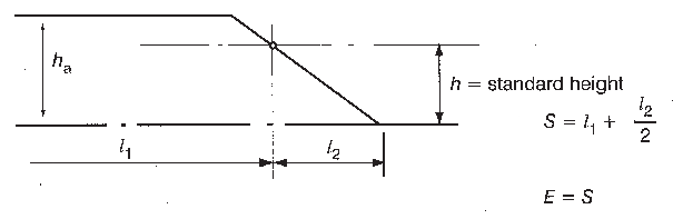
When taking account of superstructures which have sloping
end bulkheads, in the calculations of freeboards, such superstructures
should be dealt with in the following manner:
1 When the height of the superstructure, clear
of the slope, is equal to or smaller than the standard height, the
length (S) should be obtained as shown in figure 4.

Height of superstructure equal to or smaller than the standard height (h)
2 When the height is greater than the standard,
the length (S) should be obtained as shown in figure 5.
Height of superstructure greater than the standard height
3 The foregoing should apply only when the slope,
related to the base line, is 15°, the configuration should be
treated as sheer.
When the height of the superstructure, clear of the slope
is less than the standard height, its effective length (E)
should be its length (S), as obtained from paragraph
1 above, reduced in the ratio of its actual height to the standard
height.
When a poop or forecastle has sloping end bulkheads, and
sheer credit may be allowed on account of excess height, the formula
given in regulation 38(12) should
be used, the values for y and L' being as
shown in figure 6.

Sheer credit (s) for excess height
With particular regard to the length of raised quarter deck
in paragraphs (3) and (4) of this
Regulation, the following interpretation applies:
-
In a ship with a superstructure which extends over the whole
length of the freeboard deck, the part of the superstructure from
the after perpendicular up to a maximum of 0.6L may be
treated as a raised quarter-deck. In this respect, if no watertight
front bulkhead is fitted the bow may be considered to act as such.
-
The length limit imposed by paragraph
(4) of this regulation for a raised quarter-deck of less than
standard height applies to the length calculated as indicated in paragraph (3) of this Regulation.
(IACS interpretation LL.25)
The maximum effective length of 0.6L of a raised
quarter deck which is stipulated by regulation
35(4), should be measured from the after perpendicular even
where a poop is fitted in conjunction with the raised quarter-deck.
(IACS interpretation LL.26/Rev.1)
It is recommended that continuous hatchways may be treated
as a trunk in the freeboard computation provided regulation 36 is complied with in all respects.
The trunk deck stringer referred to in regulation 36(1)(b) may be fitted outboard
of the trunk side bulkhead in association with the following:
-
.1 The stringer so formed is to provide a clear
walkway of at least 450 mm in width on each side of the ship.
-
.2 The stringer is to be of solid plate efficiently
supported and stiffened.
-
.3 The stringer is to be as high above the freeboard
deck as practicable. In the freeboard calculation, the trunk height
is to be reduced by at least 600 mm or by the actual difference between
the top of the trunk and the stringer, whichever is greater.
-
.4 Hatch cover securing appliances are accessible
from the stringer or walkway.
-
.5 The breadth of the trunk is to be measured
between the trunk side bulkheads.
-
.6
Regulation 36 is
complied with in all other respects.
Less than standard height hatch coamings on trunks
of less than standard height (Regulation
36(4))
(IACS interpretation LL.27)
In the case where the trunk height is less than standard
and the trunk hatch coamings are also of less than standard height,
or omitted entirely, doubt may arise whether the trunk hatchways are
located in position 1 or position 2 and, consequently, about the reduction
to be made in the actual trunk height. In these cases the reduction
from the actual height of trunk on account of insufficient hatch coaming
height should be taken as the difference between 600 mm and the actual
height of coaming, or 600 mm if no hatch coamings are fitted. Reduction
in the actual height of trunk should not be required in cases where
only small hatches with less than standard height are fitted in the
trunk deck for which dispensation from the requirement of standard
coaming height may be given.
(IACS interpretation LL.28)
For the purpose of applying the table “Percentage
of deduction for type 'B' ships” in regulation
37(2) it is considered that any detached superstructure abaft
midship whose after bulkhead is located 0.05L or more
forward of the after perpendicular may be treated as a detached bridge.
A superstructure whose after bulkhead is located within
0.05L from the after perpendicular should not qualify
as a detached bridge.
Any excess in the height of such a superstructure, which
does not extend to the after perpendicular, cannot be regarded as
contributing to the sheer allowance contemplated in regulation 38(12).
(IACS interpretation LL.29/Rev.1)
In applying regulation 38(5) (sheer
on complete superstructure ship), where there is an enclosed poop
or forecastle superimposed on a complete superstructure, sheer credit
should be allowed for such poop or forecastle according to the method
of regulation 38(12) as shown in figure 7.
Superstructures superimposed on a forecastle or poop
(i.e. a stepped forecastle or poop) (Regulation
38(7))
In the above the following definitions should apply:
Z
v is the end ordinate of a virtual
standard parabolic curve taken through the point “x”.
If Z
v is greater than (Z + h),
the end ordinate should be (Z + h), in which case point
“x” should be disregarded and curve 2 not taken into account.
When the length of the first tier superstructure is greater
than 0.5L, the virtual standard parabolic curve should
commence at amidships as indicated in figure
7.
(IACS interpretation LL.30)
As regulation 38(7) and (12) does
not refer to a raised quarter-deck, credit should be given for this
type of superstructure only where the height of the raised quarter-deck
is greater than the standard height of "other superstructures" as
defined in regulation 33, and only
for the amount by which the actual height of the raised quarter-deck
exceeds that standard height.
(IACS interpretation LL.16)
Where the height of a superstructure is less than standard, paragraph 12 may be applied, except that
the superstructure deck should be not less than the minimum height
of the superstructure above the virtual sheer curve at any point.
For this purpose "y" should be taken as the
difference between the actual and minimum height of the superstructure
at the end of sheer.
The final explanatory subparagraph of paragraph (12) of regulation 38 should be interpreted to read:
-
"The above formula determines the mean ordinate of a curve
in the form of a parabola tangent to the actual sheer curve of the
freeboard deck at the after end of a forecastle or at the forward
end of a poop, and intersecting the end ordinate at a point below
the superstructure deck a distance equal to the standard height of
a superstructure. The superstructure deck should not be less than
standard height above this curve at any point. This curve should be
used in determining the sheer profile for forward and after halves
of the ship."
(IACS interpretation LL.31)
Since no stipulation is made as to the height of the superstructure
referred to in regulation 38(15),
the height of this superstructure should be related to its standard
height. When the height of the superstructure or raised quarter-deck
is less than standard, the reduction should be in the ratio of the
actual to the standard height thereof.
(IACS interpretation LL.38/Rev.1)
1 When calculating the bow height, the sheer of
the forecastle deck may be taken into account, even if the length
of the forecastle is less than 0.15L, but greater than
0.07L, provided that the forecastle height is not less
than one half of standard height of superstructure as defined in regulation 33 between 0.07L and
the forward terminal.
2 Where the forecastle height is less than one
half of standard height of superstructure, as defined in regulation 33, the credit bow height may
be determined as follows:
-
.1 when the freeboard deck has sheer extending
from abaft 0.15L, by a parabolic curve having its origin
at 0.15L abaft the forward terminal at a height equal
to the midship depth of the ship, extended through the point of intersection
of forecastle bulkhead and deck, and up to a point at the forward
terminal not higher than the level of the forecastle deck. However,
if the value of the height denoted h
t in figure 9 is smaller than the value of
the height denoted h
b, then h
t may
be replaced by h
b in the available bow height
(figure 9).
-
.2 when the freeboard deck has sheer extending
for less than 0.15L or has no sheer, by a line from the
forecastle deck at side at 0.07L extended parallel to
the base line to the forward terminal (figure
10).
|
h
t
|
= |
Half standard height of superstructure as defined in regulation 33
|
|
h
t
|
= |

|
(IACS interpretation LL.43)
When applying regulation 39 to
ships which have been assigned timber freeboards the bow height should
be measured from the summer load waterline and not from the timber
summer load waterline.
When the geometric freeboard calculated in accordance with paragraph (1) is less than the minimum
freeboard allowed by paragraph (2) of
this Regulation, the corrections for winter freeboard and Winter North
Atlantic freeboard should be added to the allowed minimum summer freeboard
and not to the calculated value. Similarly, the allowance for fresh
water should be a deduction from the allowed minimum summer freeboard.
Openings in the weather deck over which cargo is stowed
should be securely closed and battened down.
The ventilators and air pipes should be efficiently protected.
Timber deck cargoes should extend over at least the entire
available length which is the total length of the well or wells between
superstructures.
Where there is no limiting superstructure at the after end,
the timber should extend at least to the after end of the aftermost
hatchway.
The timber deck cargo should extend athwartships as close
as possible to the ship side due allowance being given for obstructions
such as guard rails, bulwark stays, uprights, etc. provided any gap
thus created at the side of the ship does not exceed 4% of the breadth
(b). The timber should be stowed as solidly as possible
to at least the standard height of a superstructure other than a raised
quarter-deck.
On a ship within a seasonal winter zone in winter, the height
of the deck cargo above the weather deck should not exceed one-third
of the extreme breadth of the ship.
The timber deck cargo should be compactly stowed, lashed
and secured. It should not interfere in any way with the navigation
and necessary work of the ship.
Uprights, when required by the nature of the timber, should
be of adequate strength considering the breadth of the ship; the strength
of the uprights should not exceed the strength of the bulwark and
the spacing should be suitable for the length and character of timber
carried, but should not exceed 3 m. Strong angles or metal sockets
or equally efficient means should be provided for securing the uprights.
Timber deck cargo should be efficiently secured throughout
its length by independent overall lashings.
The spacing of the lashings should be determined by the
maximum height of the cargo above the weather deck in the vicinity
of the lashing:
-
.1 for a height of 4 m and below the spacing should
be not more than 3 m;
-
.2 for a height of 6 m and above the spacing should
be not more than 1.5 m;
-
.3 at intermediate heights the average spacing
should be obtained by linear interpolation.
Where the height of timber deck cargo exceeds 6 m the strength
of the lashings should be to the satisfaction of the Administration.
Eye plates for these lashings should be efficiently attached
to the sheer strake or to the deck stringer plate. The distance from
an end bulkhead of a superstructure to the first eye plate should
be not more than 2 m. Eye plates and lashings should be provided 0.6
metre and 1.5 m from the ends of timber deck cargoes where there is
no bulkhead.
The lashings should be capable of withstanding an ultimate
load of not less than 13,600 kg. They should be fitted with sliphooks
and turnbuckles, which should be accessible at all times.
Wire rope lashings should have a short length of long link
chain to permit the length of lashings to be regulated.
When timber is in lengths of less than 3.6 m, the spacing
of the lashings should be reduced or other suitable provisions made
to suit the length of timber.
Shackles, stretching devices and all other ancillary components
incorporated into a chain or wire rope lashing and its securings should
have a minimum ultimate load of 14,100 kg. Each component should be
proof loaded to 5,600 kg. No part should be damaged or permanently
deformed after proof loading.
Provision should be made for a safe margin of stability
at all stages of the voyage, regard being given to additions of weight,
such as those due to absorption of water and icing and to losses of
weight such as those due to consumption of fuel and stores.
Protection of crew, access to machinery spaces, etc.
In addition to the requirements of regulation
25(5), guard rails or lifelines not more than 330 mm apart
vertically should be provided on each side of the cargo deck to a
height of at least 1 m above the cargo.
In addition a lifeline, preferably wire rope, set up taut
with a stretching screw, should be provided as near as practicable
to the centre line of the ship. The stanchion supports to all guard-rails
and lifelines should be spaced so as to prevent undue sagging. Where
the cargo is uneven, a safe walking surface of not less than 600 m
in width should be fitted over the cargo and effectively secured beneath
or adjacent to the lifeline.
Steering arrangements should be effectively protected from
damage by cargo and, as far as practicable, should be accessible.
Efficient provision should be made for steering in the event of a
breakdown in the main steering arrangements.
Protection of crew, access to machinery spaces, etc.
In addition to the requirements of regulation
25(5), guard rails or lifelines not more than 330 mm apart
vertically should be provided on each side of the cargo deck to a
height of at least 1 m above the cargo.
In addition a lifeline, preferably wire rope, set up taut
with a stretching screw, should be provided as near as practicable
to the centreline of the ship. The stanchion supports to all guard
rails and lifelines should be spaced so as to prevent undue sagging.
Where the cargo is uneven, a safe walking surface of not less than
600 mm in width should be fitted over the cargo and effectively secured
beneath or adjacent to the lifeline.
Steering arrangements should be effectively protected from
damage by cargo and, as far as practicable, should be accessible.
Efficient provision should be made for steering in the event of a
breakdown in the main steering arrangements.
(IACS interpretation LL.33)
Some Administrations accept that timber freeboards may be
assigned to ships with reduced type 'B' freeboards, provided the timber
freeboards are calculated on the basis of the ordinary type 'B' freeboard.
Regulation 45(2) and (3) should
be interpreted such that the Timber Winter mark and/or the Timber
Winter North Atlantic mark are placed at the same level as the reduced
type 'B' Winter mark when the computed Timber Winter mark and/or the
computed Timber Winter North Atlantic mark fall below the reduced
type 'B' Winter mark.