
Section
1 General
1.1 General
1.1.1 The requirements
of this Chapter are to be complied with in cases where Lloyd’s
Register (LR) is requested to certify the launch and recovery appliances
for the following:
- Lifeboats ‘Survival craft’.
- Life rafts ‘Survival craft’.
- Rescue boats.
- Offshore life saving craft including hyperbaric lifeboats.
- Associated releasing arrangements.
1.1.2 Special consideration
will be given to unconventional launch and recovery life saving systems.
1.1.4 Previous Conventions
are not applicable to new davits except where such davits are replacements
for an existing ship.
1.1.5 Where LR is
required to certify a launch and recovery appliance on behalf of a
National Administration whose requirements differ from those of the
IMO Convention indicated in Ch 3, 1.1 General 1.1.3,
the requirements of the National Administration concerned are to prevail.
1.1.6 This Chapter
is the basis of approval by LR of the following types of davit:
- Roller-trackway.
- Hinged gravity.
- Stored energy.
- Single arm radial.
- Fixed arm cantilever.
- Free fall system.
1.1.7 Davit types
not included above will be specially considered.
1.2 Survival craft davits
1.2.1 For all ships
with the exception of passenger ships, lifeboats are to be boarded
and launched directly from the stowed position and the davits are
to be designed accordingly.
1.2.2 All lifeboats
fitted to passenger ships are to be boarded and launched either directly
from the stowed position or from an embarkation deck, but not both,
and the davits are to be designed accordingly.
1.2.3 The launching
mechanism is to be so arranged that it may be actuated by one person
from a position on the ship’s deck and from a position within
the lifeboat.
1.2.4 When the lowering
of a survival craft is controlled from within the craft by means of
a control wire paid off from an auxiliary drum on the winch, the remote
control mechanism is to be operationally demonstrated throughout the
full launching range of the boat to the Surveyor’s satisfaction.
1.2.5 To launch
a survival craft in either its light or loaded condition, a davit
is not to depend on any means other than gravity or stored energy
generated from a source independent of the ship’s power supplies.
This does not apply to the launching appliance for lowering free-fall
lifeboats by falls.
1.2.6 Where davit
arms are recovered by power, limit switches are to be fitted to ensure
that the power is automatically switched off before the arm reaches
the stops in order to avoid overloading either the fall or the arms,
unless the winch is designed to prevent such overloading.
1.2.7 The trackways
of roller-trackway davit types are to be inclined at an angle of not
less than 35° to the horizontal.
1.2.8 Davits are
to be designed and maintained such that they remain fully effective
under conditions of icing.
1.2.9 The ratios
of the sheave diameter and winch drum diameter to the rope diameter
are to be not less than 12:1 and 16:1 respectively for running wires.
1.2.10 The minimum
thickness of plate and sections used in davit arms and frames is to
be 6 mm.
1.2.11 Davits (including
free-fall ramps) are to be capable of safely launching their fully
equipped survival craft, both with its full complement of persons
and also in the light condition, against the ship’s trim of
10°, either fore or aft, and 20° list in either direction
occurring simultaneously.
1.2.12 Davits fitted
to ships of 20 000 gross registered tons and greater are to be capable
of safely launching a lifeboat with the parent ship making five knots
headway in calm water.
1.2.13 Single arm
radial davits are to be capable of being slewed manually.
1.2.15 A davit’s
launching winch system is to be capable of power recovery of the survival
craft with its crew (i.e. 2 or 3 persons) at a minimum speed of 0,08
m/s to its stowage position with the ship at adverse list and trim
angles of 5° and 2° respectively. In addition, auxiliary manual
means of recovery are also to be provided for this condition, see
Ch 3, 1.8 Davit winches 1.8.5. However, this does not apply to
free-fall lifeboats.
1.2.16 Davits and
their equipment are to be capable of lowering the survival craft in
a controlled manner into the water at speed not less than that obtained
by the following formula for the fully loaded condition, i.e. loaded
with its normal equipment or an equivalent mass and a distributed
mass equivalent to the number of persons it is permitted to accommodate, see
Ch 3, 1.7 Calculation of forces 1.7.6.
where
|
S
|
= |
speed of lowering, in m/s |
|
H
|
= |
height, in metres, from davit head to waterline with the ship in its
lightest sea-going condition. |
1.2.17 The minimum
lowering speed of a life raft in the light condition (i.e. fully equipped
but without persons on board), is to comply with the requirements
of the National Administration concerned. The lowering speed of other
survival craft in the light condition is to be ≥0,7 x S as
calculated in Ch 3, 1.2 Survival craft davits 1.2.16.
1.2.18 The maximum
lowering speeds for all survival craft in the light condition are
not to exceed 1,0 m/s. Furthermore, the maximum lowering speeds in
the fully loaded condition are not to exceed 1,0 and 1,3 m/s for life
rafts and lifeboats respectively, unless different values are required
by the relevant National Authority.
1.2.19 A free-fall
launching system is required to employ an alternative controlled means
of launching and a means of recovering the lifeboat by falls. Lifeboats
are not to be launched in the free-fall mode where there is a risk
of the presence of ice or insufficient depth of water. A notice to
this effect should be displayed at the operating station.
1.2.20 The davits
are to be arranged so that harmful accelerations are not experienced
by the lifeboat occupants during launching.
1.2.21 Harmful
acceleration is the rate of change of velocity experienced by the
occupants which is in excess of levels calculated in accordance with
the IMO test requirements of Ch 3, 1.1 General 1.1.3,
or other recognised National or International Standards.
1.2.22 Where conditions
are such that the free-fall operating mode is not necessary, a free-fall
lifeboat is to be capable of being safely lowered in a ‘controlled’
manner with the ship inclined at a maximum list of 5° and a maximum
trim of 2°.
1.2.23 The free-fall
launching arrangement is to be a rigid structure with a ramp angle
and length sufficient to ensure that the lifeboat effectively clears
the ship.
1.2.24 Where a
survival craft is designed to float free from its launching appliance,
either by a weak link or by a hydrostatic release unit, the float
free release of the survival craft from the stowed position is to
be automatic.
1.3 Rescue boat davits
1.3.1 This Section
covers davits that are used for launching and recovering lifeboats
which may also be used as rescue boats, as well as davits that are
solely dedicated to launching and recovering rescue boats only.
1.3.2 In addition
to the requirements for survival craft davits in Ch 3, 1.2 Survival craft davits, all rescue boat davits are to meet the following requirements:
-
The davits are to be
capable of launching the rescue boat from the stowed position in not
more than five minutes.
-
The davits and winches
are to be capable of power hoisting the rescue boat, loaded with its
full rescue boat complement and equipment, from the water at a rate
of not less than 0,3 m/s.
1.3.3 For davits
that are solely dedicated to the launching and recovery of rescue
boats, special consideration may be given to recovery arrangements
which are dependent on the ship’s power supply. These davits
may be equipped for single point hoisting.
1.3.4 Special consideration
may be given to the launching mechanism of a dedicated rescue boat
being operable solely from a position on the ship’s deck.
1.4 Offshore life saving systems
1.4.2 The following
additional requirements are applicable to any launch and recovery
system used for handling survival craft (including hyperbaric lifeboats)
and rescue boats, fitted to either fixed or mobile offshore installations.
It should be noted that some National Authorities may have different
requirements.
1.4.3 Davits are
to be capable of launching a fully equipped survival craft with a
full complement of persons against a high or low side list and trim
of the installation of 15° simultaneously. Notwithstanding the
foregoing requirement, davits intended for column-stabilised mobile
drilling units should be capable of operating at the list and trim
resulting from any damaged condition required by the relevant Chapter
of the current IMO Code for the Construction and Equipment of
Mobile Offshore Drilling Units (MODU Code).
1.4.4 All gravity
davits are to be designed for a positive turning-out moment when the
installation is adversely inclined at an angle of 25° high side
list (HSL).
1.4.5 Davits for
rescue boats are to be equipped with suitable shock absorbing or motion
compensating arrangements to facilitate launching and hoisting of
the boat in heavy seas.
1.4.6 Launching
against high side list is not required for rescue boats. Otherwise,
launching should be performed with the aid of gravity or with an arrangement
coupled to the emergency power source.
1.5 Plan approval requirements
1.6 Safety and stress factors
1.6.1 The minimum safety factors (SF) required with respect to the minimum
ultimate tensile stress (σu) of the materials used in the construction of the
primary structural members and the loose gear are given in Table 3.1.1 Minimum safety factors.
Table 3.1.1 Minimum safety factors
| Item
|
SF required on σu
|
| Direct stress
|
Shear stress
|
| Structural components
|
4,5
|
7,8
|
| Loose gear
|
6,0
|
10,3
|
| Release hooks
|
6,0
|
10,3
|
1.6.2 For steel
in which σy/σu ≤0,7, the allowable
compressive stress, σa, in primary structural members
is given by the following expression:
where
|
σcr
|
= |
critical compressive stress |
|
σu
|
= |
minimum ultimate tensile stress, N/mm2
|
|
σy
|
= |
yield stress, N/mm2
|
SF is given in Table 3.1.1 Minimum safety factors.
1.6.3 Steels in which σy/σu > 0,7 will be specially
considered.
1.6.4 The minimum stress factor to be applied for the design test load case for
prototype and production testing is to be taken as 0,85 (see
Ch 4, 2.15 Load combinations 2.15.5.(d) and Table 4.2.6 Stress factor, F
, load case
4). The requirements for prototype testing are defined in Ch 3, 1.12 Testing 1.12.2. The requirements for
production testing are defined in Ch 3, 1.12 Testing 1.12.3. The allowable stresses to
be considered for the prototype and production test load cases are defined in the
applicable Chapters of the Code, i.e.:
- Ch 4, 2.17 Allowable stress – Elastic failure;
- Ch 4, 2.18 Allowable stress – Compression, torsional and bending members;
- Ch 4, 2.19 Crane jibs – Overall stability;
- Ch 4, 2.20 Slenderness ratio;
- Ch 4, 2.21 Allowable stress – Plate buckling failure;
- Ch 4, 2.22 Allowable stress – Buckling failure of thin walled cylinders; and
- Ch 4, 2.23 Allowable stress – Joints and connections
1.7 Calculation of forces
1.7.1 Force diagrams
or calculations are required for the davit arm in its lowest position
subject to both 20° low side list (LSL) (up to 30° for tankers
in the damaged condition) for both the SWL and the weight of the davit
arm. The torsion and lateral bending effects due to the 10° trim
component are also to be considered (20° list component for radial
arm davits).
1.7.2 Calculations
are also required for the davit arm in its stowed position to ensure
that a positive turning out moment exists with the ship at 20°
HSL, see
Figure 3.1.1 Davit arm turning-out
moments.
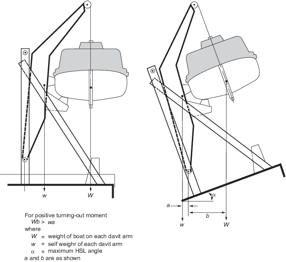
Figure 3.1.1 Davit arm turning-out
moments
1.7.3 The tension
in the boat falls and forces in the davit arms are to be calculated
using the appropriate friction allowance of the blocks and sheaves
for both the following cases:
-
The turning out/lowering
of the fully equipped lifeboat and its total complement of persons,
where applicable. For a roller-track system, see
Figure 3.1.2 Roller-track system, maximum wire rope tension.
-
The recovering of the
fully equipped lifeboat and its crew to either the stowed position
or to the embarkation deck.
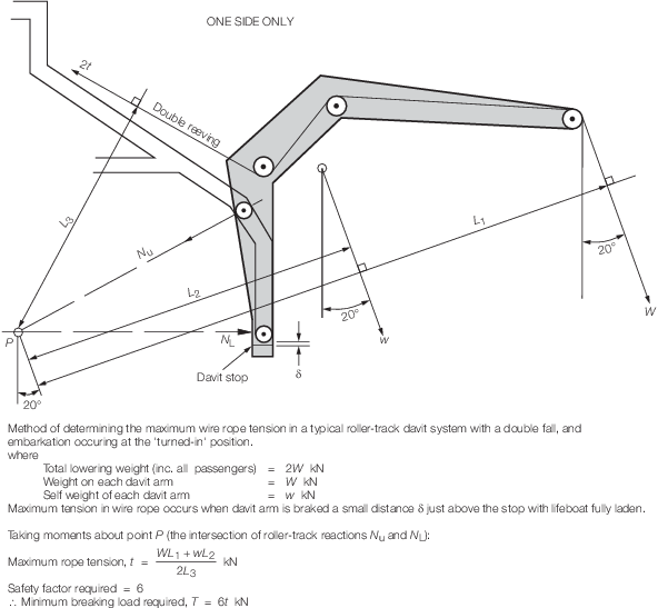
Figure 3.1.2 Roller-track system, maximum wire rope tension
1.7.5 The resultant
loads on each of the blocks or sheaves in the rig are also to be determined
by appropriate force diagrams or calculation.
1.7.6 For design
purposes, the weight of one person is taken as 82,5 kg, except for
passenger vessels which are to use 75 kg.
1.7.7 Friction in
each sheave and pivot pin is to be taken as 5 per cent. However, sheaves
having roller bearings may be taken as 2 per cent.
1.8 Davit winches
1.8.1 In general,
davit winches are to comply with the requirements of Ch 9 Machinery where applicable.
1.8.2 Winch structural
members are to be designed to have a minimum safety factor of 4,5
in respect of the minimum ultimate tensile stress of the material
when the maximum working load is applied.
1.8.3 Winches with
multiple drums are to be so arranged that all the falls wind on or
off the drums at the same rate when either hoisting or lowering.
1.8.4 Winches are
to be provided with an efficient hand gear arrangement to enable the
survival craft or rescue boat to be recovered manually. The hand gear
handles and wheels are not to be rotated by the moving parts of the
winch when being operated by power. This does not apply to free-fall
lifeboats.
1.8.5 Every davit
winch is to be fitted with brakes capable of stopping the maximum
speed of descent of the survival craft or rescue boat and of holding
it securely when loaded with its full complement of persons and equipment.
1.8.6 Winch brake
pads are to be protected from water and oil, and an efficient means
of preventing them from freezing is to be provided.
1.9 Loose gear
1.9.1 For the purposes
of this Chapter, the loose gear consists of the survival craft or
rescue boat falls together with the blocks, shackles, links, padeyes,
swivels, fastenings or any other fitting attached to the falls.
1.9.3 Bowsing, griping
and tricing tackles are not included in LR’s approval. However,
their adequacy should be operationally demonstrated to the Surveyor’s
satisfaction.
1.9.5 Wire rope
falls are to be galvanised or heavily greased and are to be of a rotation
resistant construction.
1.9.6 The use of
stainless steel wire ropes will be specially considered, but generally
are to be of a higher alloy composition, e.g. Inconel 625, Incoloy
alloy 825, Duplex Ferralium 255. They are to comply with the requirements
of 1.13.6. It is recommended that lower grades of stainless steel
(e.g. SUS 304, SUS 316, etc.) are not used for lifeboat falls as they
are subject to stress corrosion cracking, crevice corrosion and pitting.
1.9.7 The falls
are to be of sufficient length to enable the survival craft or rescue
boat to reach the water with three full turns remaining on the winch
drum with the ship in her lightest sea-going condition and listed
20° in the adverse direction.
1.9.8 The ends of
the falls are to be securely attached to the winch drum.
1.9.9 Wire rope
terminations are to be manufactured and the termination process is
to be in accordance with the requirements of the manufacturer and/or
a National or International Standard. Wire rope grips are not to be
used as the primary load bearing termination. Where used, the number
of grips and their tightening torque is to be strictly in accordance
with the manufacturer’s and/or the National/International Standard
requirements. The tightening torque is to be regularly checked.
1.9.10 Blocks,
shackles, swivels and other fittings are to be designed to have a
minimum safety factor in accordance with Table 3.1.1 Minimum safety factors with respect to the minimum ultimate tensile stress of
the materials when the maximum working load is applied.
1.9.11 Each item
of loose gear is to be proof-tested to 2,2 times its SWL (2,5 times
its SWL for use offshore).
1.9.12 In addition,
loose gear is to be prototype tested to 6 times its SWL to demonstrate
its structural adequacy against failure.
1.10 Release hooks
1.10.1 Release
hooks may be of the type fixed to the wire fall. These are generally
used for single point suspension or of the type permanently attached
to the craft being launched.
1.10.2 Release
hooks for davit launched life rafts and dedicated inflatable/semi-rigid
rescue boats are to comply with the following requirements:
-
Only one type of release
hook, or other release mechanism, is to be fitted to similar survival
craft or rescue boats on board a ship.
-
Each release hook and
its mechanism is to be designed to have a minimum safety factor in
accordance with Table 3.1.1 Minimum safety factors, with
respect to the minimum ultimate tensile stress of the materials used
when the maximum safe working load of the hook is applied.
-
The release mechanism
is to be capable of releasing the craft in either the ‘off-load’
condition, i.e. when it is waterborne or when there is no load on
the hooks, or, in the ‘on-load’ condition (however, this
capability is to be adequately protected against accidental or inadvertent
use).
-
Release hooks are to
be designed and maintained such that they remain fully effective under
conditions of icing.
-
A prototype release
hook and its mechanism is to be proof loaded to 6 times its SWL, holding
this load for at least 5 minutes. After removal of the load, the release
mechanism is to be dismantled and examined for damage.
-
A prototype release
hook and its mechanism is to be proof-load tested by subjecting it
to a steadily increasing load until failure occurs. This breaking
load is to be recorded.
-
Additionally, each
release hook and its mechanism is to be ‘dynamically’
tested by lowering a proof-load of 1,1 times its SWL and abruptly
applying the brakes when the lowering speed has been reached.
1.10.3 Release
hooks for lifeboats, combined liferaft/rescue boats and rigid rescue
boats are to comply with the requirements of Ch 3, 1.10 Release hooks 1.10.2 and, in addition, a mechanism is to be fitted to each
lifeboat or rescue boat to ensure that each hook is released simultaneously.
The effectiveness of this is to be demonstrated to the Surveyor’s
satisfaction.
1.11 Materials
1.11.3 Where a ship is intended for service in more severe environments (e.g. ice
breakers in polar waters) the Charpy V-notch impact test requirements will be specially
considered based on the minimum service temperature specified.
1.11.5 Steel or
spheroidal graphite iron materials may be accepted for cast components.
Grey cast iron is not a suitable material and may only be accepted
for components after special consideration of the proposed application.
1.12 Testing
1.12.2 Prototype
testing of survival craft (excluding free-fall) and rescue boat davits
and winches is to comply with the following requirements:
-
The davit with the
arm in the outboard position is to be statically tested to 2,2 times
the SWL. This test load is to be applied 10° either side of the
vertical in the fore and aft direction, first with 0° list and
then with both 20° HSL and 20° LSL conditions simulated.
-
The davit is to be
dynamically tested to 1,1 times the maximum load appropriate to the
part of the operating cycle concerned, over the full operating range
with the ship at 0° list. This test is to be repeated with a 20°
HSL and 10° trim condition simulated e.g. for a lifeboat/rescue
boat davit fitted to a passenger ship where embarkation occurs with
the davit arm in the turned-out position, the tests are to be conducted
with the loads indicated in Table 3.1.2 Prototype: Dynamic test
factors.
-
The dynamic tests in Ch 3, 1.12 Testing 1.12.2.(b) are to be repeated with a test
load equal to the weight of the fully equipped lightest craft, without
persons, through at least one complete operating cycle in order to
demonstrate satisfactory functioning of the davit under light conditions.
-
For davits intended
for installation on oil tankers, chemical tankers or gas carriers,
all the foregoing tests are to be carried out at the final list angle
(LSL only) where this is found to exceed 20°.
-
A ‘static’
test load of 1,5 times safe working moment (SWM) is to be held on
the winch brakes with the maximum number of turns of rope on the winch
drum. This is to be demonstrated through at least one revolution of
the winch drum.
-
A ‘dynamic’
load test of 1,1 times SWL is to be lowered at maximum speed for at
least three metres and stopped by abruptly applying the winch brakes.
This test load should not drop more than one metre after the brake
is applied and is to be repeated several times to achieve a cumulative
lowering distance of at least 150 m.
-
A ‘recovery’
test is to be performed if the winch is to be used with a rescue boat
to demonstrate that the fully loaded rescue boat can be recovered
at a rate not less than 0,3 m/sec. It should be demonstrated that
the winch hand recovery gear can recover a maximum load equivalent
to a fully loaded boat.
-
After completion of
the tests, the winch should be stripped for inspection.
Table 3.1.2 Prototype: Dynamic test
factors
| Boat position
|
Lifeboat
|
Rescue boat
|
| From
|
To
|
| Stowed
|
Embarkation
|
1,1 × P
1
|
1,1 × P
1
|
| Embarkation
|
Sea level
|
1,1 × P
2
|
1,1 × P
1
|
| Sea level
|
Embarkation
|
1,1 × P
1
|
1,1 × P
2
|
| Embarkation
|
Stowed
|
1,1 × P
1
|
1,1 × P
1
|
| Symbols
|
|
P
1
|
= |
weight of the lifeboat or rescue boat (as
appropriate) with full equipment and weight of operating crew |
|
P
2
|
= |
weight of the lifeboat or rescue boat with full
equipment and weight of crew and weight of passengers (i.e.
SWL) |
|
1.12.3 Production
testing of survival craft (excluding free-fall) and rescue boat davits
and winches is to comply with the following requirements:
-
A ‘static’
load test of 2,2 times SWL is to be held by the davit in its fully
outboard position at 0° list (2,5 times SWL for use offshore).
-
A ‘static’
load test of 1,5 times SWL is to be held on the winch brakes.
-
Each block and shackle
supplied with the davit is to be tested to 2,2 times their individual
SWL (2,5 times SWL for use offshore). When they are not supplied with
a manufacturer’s certificate, tests are to be witnessed and
LR’s certificate issued.
-
All fall ropes should
be supplied with a manufacturer’s certificate of test indicating
the breaking strength of the rope, which is to be not less than 6
times the maximum tension.
1.12.4 On board
(installation) testing of survival craft (excluding free-fall) and
rescue boat davits and winches is to comply with the following requirements:
-
A ’dynamic’
lowering test of 1,1 times SWL is to be carried out with the davit
in the outboard position. When the maximum lowering speed is reached,
the brakes are to be abruptly applied to demonstrate the adequacy
of both the attachment to the supporting structure in way of the winch
and to the davits. For ships with inboard embarkation, the test is
to be conducted from this position.
-
A ’dynamic’
lowering test is to be performed with the lifeboat or rescue boat
in the fully loaded condition to demonstrate that its entry into the
water is not less than the figure calculated from the expression in Ch 3, 1.2 Survival craft davits 1.2.16 and is within the limit detailed
in Ch 3, 1.2 Survival craft davits 1.2.18.
-
The above test is to
be repeated with the lifeboat or rescue boat in the ’light’
condition (i.e. equipped but without personnel) to ensure that the
frictional resistance of the winch, fall, blocks, etc. can be overcome.
In this condition, the minimum entry speed of the boat is to comply
with the requirements of Ch 3, 1.2 Survival craft davits 1.2.17.
-
For a life raft in
the ‘light’ condition, it is generally only necessary
to demonstrate that it has sufficient weight to overcome the friction
in the davit reeving system.
-
It is to be demonstrated
to the Surveyor’s satisfaction that the davits and winches are
able to recover and return the survival craft to its stowage position,
with satisfactory operation of limit switches, and be properly secured.
Additionally, it is to be demonstrated that the survival craft can
be recovered and returned to its stowage position using the emergency
hand gear.
-
For rescue boat launching
appliances, it is to be demonstrated that the rescue boat, with weight
equal to its rescue complement, can be recovered using the davit winch
at a rate not less than 0,3 m/s.
-
It is to be demonstrated
to the Surveyor’s satisfaction that the remote control release
mechanism inside the survival craft operates correctly.
1.12.5 Prototype
testing of free-fall launching ramps and associated controlled launch
auxiliary davits is to be carried out as follows:
-
The ramp structure
is to be tested in applying a static load of 2,2 times SWL in positions
along the ramp which gives maximum stress in the ramp structure with
simulated shipboard 20° HSL and LSL and 10° fore and aft trim.
-
The auxiliary davit
arm is to be statically tested on the ramp and in its outboard position
to 2,2 times SWL, with simulated shipboard 20° HSL and LSL and
10° fore and aft trim.
-
Additionally, the auxiliary
davit arm is to be dynamically tested on the ramp to 1,1 times the
maximum load appropriate to the part of the operating cycle concerned,
over the full operating range with the ship at 0° list.
-
The tests indicated
in Ch 3, 1.12 Testing 1.12.2.(c), Ch 3, 1.12 Testing 1.12.2.(d), Ch 3, 1.12 Testing 1.12.2.(e), Ch 3, 1.12 Testing 1.12.2.(f) and Ch 3, 1.12 Testing 1.12.2.(h) are
also to be conducted for free-fall systems.
-
The pressure parts
of the hydraulically operated lifting system are to be hydrostatically
tested to 1,5 times design pressure.
-
If the ramp is an adjustable
type, it is to be demonstrated that it may be satisfactorily adjusted
with the free-fall lifeboat loaded to 1,2 times its fully laden weight.
1.12.6 Production
and installation testing of a free-fall system is to be carried out
in accordance with Ch 3, 1.12 Testing 1.12.3 and Ch 3, 1.12 Testing 1.12.4 except as follows:
-
During a free-fall
launch of the lifeboat, the water entry speed is to be such that no
harmful forces are experienced by the lifeboat occupants.
-
Each new free-fall
lifeboat is to be loaded to 1,1 times its fully laden weight and launched
by free fall with the ship on an even keel and in its lightest sea-going
condition.
-
During the ‘controlled’
mode of launching, the free-fall lifeboat is to be loaded to 1,1 times
SWL and released by the operation of the launching controls on deck.
When the lifeboat has reached its maximum lowering speed of not greater
than 1,3 m/s, the brake is to be applied abruptly in order to demonstrate
the attachment and adequacy of the support structure in way of the
davit and winch.
-
It is to be demonstrated
that the lifeboat may be recovered to its stowage position and can
be safely and properly secured.
1.12.7 Periodical
re-testing in accordance with the installation testing described in Ch 3, 1.12 Testing 1.12.4 and Ch 3, 1.12 Testing 1.12.6 is to be carried out every five years. Attention is drawn
to the applicable requirements in the IMO Life Saving Appliance (LSA)
Code, as amended.
1.12.8 After any
repair affecting the strength of the davit or winch, the appliance
is to be subject to the ‘dynamic’ loaded lowering test
described in Ch 3, 1.12 Testing 1.12.4.
1.13 Inspection and maintenance
1.13.1 Every survival
craft or rescue boat davit is to be visually inspected once a week
by the crew to ensure they are at all times ready for immediate use.
1.13.2 It is recommended
that rescue boats, including lifeboats which double as rescue boats,
are to be launched using their davits at least once every month. In
all cases, this recommendation is to be complied with at least once
every three months for both lifeboats and rescue boats. For lifeboats
installed on offshore platforms, this recommendation is to be complied
with at least once every two months.
1.13.3 Every davit
and winch is to be constructed so as to reduce routine maintenance
to a minimum. Those parts requiring regular maintenance are to be
readily accessible and easily maintained by the ship’s crew.
Where possible, the use of maintenance free sealed bearings is to
be adopted.
1.13.4 All parts
subject to wear should be examined with respect to the manufacturer’s
recommendations and repaired or replaced as necessary.
1.13.5 All davits
and winches are to be adequately protected against corrosion and are
to be constructed so as to prevent incendive friction or impact sparking
during launching.
1.13.6 Davit falls
are to be inspected periodically and must be renewed every five years
or sooner should their condition deteriorate.
1.13.7 A record
of maintenance, repair and test should be kept for each davit.
1.14 Certification and documentation
1.14.1 The minimum
requirements for the issue of LR certification for life-saving launch
and recovery appliances are as indicated in Ch 1, 1.2 Certification 1.2.5.
1.14.3 When LR
is authorised by Governments or National Administrations to issue,
on their behalf, statutory Safety Equipment Certificates on LR classed
ships, all tests are required to be witnessed by LR.
1.14.4 Life-saving
launch and recovery appliances are an integral aspect of a ship’s
list of safety equipment which is to satisfy LR’s requirements
prior to the issue of Safety Equipment Certification and Record of
Safety Equipment (Report S.E.1).
|