
Section
11 Machinery strengthening requirements for navigation in multi-year ice conditions
– Ice Classes PC1, PC2, PC3, PC4, PC5, PC6, PC7 and Icebreaker
11.1 Application
11.1.1 The
contents of this Section apply to main propulsion, steering gear,
emergency and essential auxiliary systems essential for the safety
of the ship and the survivability of the crew and systems and equipment
required by assigned optional classification notations, e.g. navigational
equipment associated with the notations NAV1 or IBS.
11.1.2 For PC6 and PC7, the requirements will be considered with
respect to compliance with the Finnish - Swedish Ice Class Rules.
11.2 Drawings and particulars to be submitted
11.2.1 The
following drawings and particulars to be submitted:
-
Details of the
environmental conditions and the required ice class for the machinery,
if different from ship's ice class.
-
Detailed drawings
of the main propulsion machinery. Description of the main propulsion,
steering, emergency and essential auxiliaries are to include operational
limitations. Information on essential main propulsion load control
functions.
-
Description detailing
how main, emergency and auxiliary systems are located and protected
to prevent problems from freezing, ice and snow and evidence of their
capability to operate in intended environmental conditions.
-
Calculations
and documentation indicating compliance with the requirements of this
Section.
11.3 System design
11.3.1 Systems,
subject to damage by freezing, are to be drainable.
11.3.2 Single
screw vessels classed PC1 to PC5 inclusive are to have means provided
to ensure sufficient vessel operation in the case of propeller damage
including CP mechanism.
11.4 Materials exposed to sea-water
11.4.1 Materials
exposed to sea-water, such as propeller blades, propeller hub and
blade bolts are to have an elongation not less than 15 per cent on
a test piece the length of which is five times the diameter. Charpy
V impact test are to be carried out for other than bronze and austenitic
steel materials. Test pieces taken from the propeller castings are
to be representative of the thickest section of the blade. An average
impact energy value of 20 J taken from three Charpy V tests is to
be obtained at minus 10°C.
11.5 Materials exposed to sea-water temperature
11.5.1 Materials
exposed to sea-water temperature are to be of steel or other approved
ductile material. An average impact energy value of 20 J taken from
three tests is to be obtained at minus 10°C.
11.6 Materials exposed to low air temperature
11.6.1 Materials of essential components exposed to low air temperature shall be
of steel or other approved ductile material. An average impact energy value of 20 J
taken from three Charpy V tests is to be obtained at 10°C below the lowest design
temperature. See also the Rules for the Winterisation of Ships, July 2022 .
11.7 Propeller ice interaction
11.7.1 These
Rules cover open and ducted type propellers situated at the stern
of a vessel having controllable pitch or fixed pitch blades. Ice loads
on bow propellers and pulling type propellers are to receive special
consideration. The given loads are expected, single occurrence, maximum
values for the whole ship's service life for normal operational conditions.
These loads do not cover off-design operational conditions, for example
when a stopped propeller is dragged through ice. These Rules apply
also for azimuthing (geared and podded) thrusters considering loads
due to propeller ice interaction. However, ice loads due to ice impacts
on the body of azimuthing thrusters are not covered by this Section.
11.7.2 The
loads given in Pt 8, Ch 2, 11.7 Propeller ice interaction are total
loads (unless otherwise stated) during ice interaction and are to
be applied separately (unless otherwise stated) and are intended for
component strength calculations only. The different loads given here
are to be applied separately.
11.7.3
F
b is a force bending a propeller blade backwards when the propeller
mills an ice block while rotating ahead. F
f is
a force bending a propeller blade forwards when a propeller interacts
with an ice block while rotating ahead.
11.8 Ice class factors
11.8.1
Table 2.11.1 Propeller ice loads index lists the design ice
thickness and ice strength index to be used for estimation of the
propeller ice loads.
Table 2.11.1 Propeller ice loads index
|
Ice Class
|
H
ice
, in metres
|
S
ice
|
S
qice
|
|
PC1
|
4,0
|
1,2
|
1,15
|
|
PC2
|
3,5
|
1,1
|
1,15
|
|
PC3
|
3,0
|
1,1
|
1,15
|
|
PC4
|
2,5
|
1,1
|
1,15
|
|
PC5
|
2,0
|
1,1
|
1,15
|
|
PC6
|
1,75
|
1,0
|
1,00
|
|
PC7
|
1,5
|
1,0
|
1,00
|
| where
|
|
H
ice
|
= |
ice thickness for machinery strength design |
|
|
S
ice
|
= |
ice strength index for blade ice force |
|
|
S
qice
|
= |
ice strength index for blade ice torque |
|
11.9 Design ice loads for open propeller
11.9.1 The
maximum backward blade force, F
b, is to be
taken as:
when D < D
limit
|
F
b
|
= |
 kN kN |
when D ≥ D
limit
|
F
b
|
= |
 kN kN |
where
|
D
limit
|
= |
0,85 (H
ice)1,4
|
|
n
|
= |
the
nominal rotational speed in rev/sec (at MCR free running condition)
for CP-propeller and 85 per cent of the nominal rotational speed (at
MCR free running condition) for a FP-propeller (regardless of driving
engine type). |
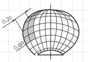
11.9.2
F
b is to be applied as a uniform pressure distribution to an
area on the back (suction) side of the blade for the following load
cases:
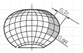
-
Load case 1:
from 0,6R to the tip and from the blade leading edge
to a value of 0,2 chord length
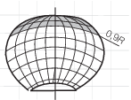
-
Load case 2:
a load equal to 50 per cent of the F
b is to
be applied on the propeller tip area outside of 0,9R
-
Load case 5:
for reversible propellers, a load equal to 60 per cent of the F
b is to be applied from 0,6R to the tip and from
the blade trailing edge to a value of 0,2 chord length.
See load cases 1, 2, and 5 in Table 2.11.4 Load cases for open
propeller.
11.9.3 The
maximum forward blade force, F
f, is to be
taken as:
when D < D
limit
|
F
f
|
= |
 kN kN
|
when D ≥ D
limit
|
F
f
|
= |
 kN kN
|
where
|
D
limit
|
= |
 m m
|
|
d
|
= |
propeller
hub diameter, in metres |
|
D
|
= |
propeller
diameter, in metres |
|
EAR
|
= |
expanded
blade area ratio |
|
Z
|
= |
number
of propeller blades. |
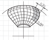
11.9.4
F
f is to be applied as a uniform pressure distribution to an
area on the face (pressure) side of the blade for the following load
cases:
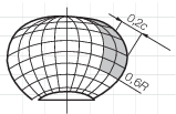
-
Load case 3:
from 0,6R to the tip and from the blade leading edge
to a value of 0,2 chord length.
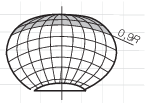
-
Load case 4:
a load equal to 50 per cent of F
f is to be
applied on the propeller tip area outside of 0,9R.
-
Load case 5:
for reversible propellers a load equal to 60 per cent of F
f is to be applied from 0,6R to the tip and from
the blade trailing edge to a value of 0,2 chord length.
See load cases 3, 4, and 5 in Table 2.11.4 Load cases for open
propeller.
11.9.5 The
blade spindle torque, Q
smax, around the spindle
axis of the blade fitting is to be calculated both for the load cases
described in Pt 8, Ch 2, 11.9 Design ice loads for open propeller 11.9.1 and Pt 8, Ch 2, 11.9 Design ice loads for open propeller 11.9.3 for F
h and F
f. If these spindle torque values are less than
the default value given below, the default minimum value is to be
used:
where
|
C
0,7
|
= |
length of the blade chord at 0,7R radius, in m
|
|
F
|
= |
F
h or F
f whichever has the greater absolute
value.
|
11.9.6 The
maximum propeller ice torque applied to the propeller is to be taken
as:
when D < D
limit
|
Q
max
|
= |
 kNm kNm |
when D ≥ D
limit
|
Q
max
|
= |
 kNm kNm |
where
|
S
qice
|
= |
ice strength index for blade ice torque |
|
P
0,7
|
= |
propeller pitch at 0,7R, in m
|
|
|
= |
for CP propellers, P
0,7 is to correspond
to MCR in bollard condition. If not known, P
0,7 is
to be taken as 0,7P
0,7n
|
|
P
0,7n
|
= |
propeller pitch at MCR free running condition |
|
t
0,7
|
= |
maximum thickness at 0,7R
|
|
n
|
= |
the rotational propeller speed, in rev/sec, at bollard condition.
If not known, n is to be taken as follows: for CP propellers and FP
propellers driven by turbine or electric motor = n
n
|
|
for FP propellers driven by engine |
= |
0,85n
n
|
|
n
n
|
= |
the nominal rotational speed at MCR, free running condition. |
11.9.7 The
maximum propeller ice thrust applied to the shaft is to be taken as:
11.10 Design ice loads for ducted propellers
11.10.1 The
maximum backward blade force, F
b is to be
taken as:
when D < D
limit
|
F
b
|
= |

|
when D ≥ D
limit
|
F
b
|
= |

|
where
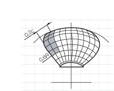
11.10.2
F
b is to be applied as a uniform pressure distribution
to an area on the back side for the following load cases:
-
Load case 1:
on the back of the blade from 0,6R to the tip and from
the blade leading edge to a value of 0,2 chord length
-
Load case 5:
for reversible rotation propellers a load equal to 60 per cent of F
b is applied on the blade face from 0,6R to
the tip and from the blade trailing edge to a value of 0,2 chord length.
See load cases 1 and 5 in Table 2.11.5 Load cases for ducted
propeller.
11.10.3 The
maximum forward blade force, F
f, is to be
taken as:
when D ≤ D
limit
|
F
f
|
= |
 kN kN
|
when D > D
limit
|
F
f
|
= |
 kN kN
|
where
|
D
limit
|
= |
 m. m.
|
11.10.4
F
f is to be applied as a uniform pressure distribution
to an area on the face (pressure) side for the following load cases:
-
Load case 3:
on the blade face from 0,6R to the tip and from the blade
leading edge to a value of 0,5 chord length.
-
Load case 5:
a load equal to 60 per cent F
f is to be applied
from 0,6R to the tip and from the blade leading edge
to a value of 0,2 chord length.
See load cases 3 and 5 in Table 2.11.5 Load cases for ducted
propeller.
11.10.5 The
maximum propeller ice torque, Q
max, applied
to the propeller is to be taken as:
when D ≤ D
limit
|
Q
max
|
= |
 kNm kNm |
when D > D
limit
|
Q
max
|
= |
 kNm kNm |
where
|
D
limit
|
= |
1,8H
ice in metres
|
|
n
|
= |
the
rotational propeller speed, in rps, at bollard condition. If not known, n is to be taken as follows: for CP propellers and FP propellers
driven by turbine or electric motor = n
n
|
|
for FP propellers driven by engine |
= |
0,85n
n
|
|
n
n
|
= |
the nominal rotational speed at MCR at free running condition |
|
P
0,7
|
= |
for CP propellers, propeller pitch, P
0,7 is
to correspond to MCR in bollard condition. If not known, P
0,7 is to be taken as 0,7P
0,7n
|
|
P
0,7n
|
= |
propeller pitch at MCR free running condition. |
11.10.6 The
spindle torque for CP-mechanism design, Q
smax,
around the spindle axis of the blade fitting is to be calculated for
the load case described in Pt 8, Ch 2, 11.7 Propeller ice interaction.
If these spindle torque values are less than the default value given
below, the default value is to be used:
where
|
C
0,7
|
= |
the length of the blade section at 0,7R
|
|
F
|
= |
F
b or F
f whichever has the greater absolute
value.
|
11.10.7 The
maximum propeller ice thrust (applied to the shaft at the location
of the propeller) is to be taken as:
11.11 Design loads on propulsion line – Torque
11.11.1 The
propeller ice torque excitation for shaft line dynamic analysis is
to be described by a sequence of blade impacts which are of half sine
shape and occur at the blade. The torque due to a single blade ice
impact as a function of the propeller rotation angle is to be taken
as:
|
Q(φ) |
= |

|
where
Table 2.11.2 Torque load factors
| Torque excitation
|
Propeller-ice interaction
|
C
q
|
αi.
|
| Case 1
|
Single ice
block
|
0,50
|
45
|
| Case 2
|
Single ice
block
|
0,75
|
90
|
| Case 3
|
Single ice
block
|
1,00
|
135
|
| Case 4
|
Two ice blocks
with 45 degree phase in rotation angle
|
0,50
|
45
|
11.11.2 The
total ice torque is obtained by summing the torque of single blades
taking into account the phase shift 360°/Z. The number
of propeller revolutions during a milling sequence is to be obtained
with the formula:
where

Figure 2.11.1 The shape of the propeller ice torque excitation for 45,
90, 135 degrees single blade impact sequences and 45 degrees double
blade impact sequence (two ice pieces) on a four bladed propeller
11.11.3 The milling torque sequence duration is not valid for pulling bow
propellers, which are subject to special consideration. The response torque at any shaft
component is to be analysed considering excitation torque Q(φ) at the propeller,
actual engine torque, Qe, and mass elastic system. Where
Qe is the actual maximum engine torque at considered speed.
11.11.4 The design torque, Qr, of the shaft component is to be
determined by means of torsional vibration analysis of the propulsion line. Calculations
are to be carried out for all excitation cases given above and the response is to be
applied on top of the mean hydrodynamic torque in bollard condition at considered
propeller rotational speed.
11.12 Design loads on propulsion line – Maximum response thrust
11.12.1 The
maximum thrust along the propeller shaft line is to be calculated
with the formulae below. The factors 2,2 and 1,5 take into account
the dynamic magnification due to axial vibration. Alternatively, the
propeller thrust magnification factor may be calculated by dynamic
analysis.
Maximum shaft thrust forwards
Maximum shaft thrust backwards
where
|
T
f
|
= |
maximum forward propeller ice thrust, in kN. |
Table 2.11.3 Propeller thrust factor
| Propeller type
|
T
n
|
| CP propellers
(open)
|
1,25T
|
| CP propellers
(ducted)
|
1,10T
|
| FP propellers
driven by turbine or electric motor
|
T
|
| FP propellers driven
by engine (open)
|
0,85T
|
| FP propellers
driven by engine (ducted)
|
0,75T
|
| Symbols
|
|
T
|
= |
nominal propeller thrust at MCR at free running open
water conditions |
|
Table 2.11.4 Load cases for open
propeller
| Load case
|
Force
|
Loaded area
|
Right handed propeller blade seen
from back
|
| Load case 1
|
F
b
|
Uniform pressure
applied on the back of the blade (suction side) to an area from 0,6R
to the tip and from the leading edge to 0,2 times the chord length.
|
|
| Load case 2
|
50% of F
b
|
Uniform pressure applied on the back of the blade
(suction side) on the propeller tip area outside of 0,9R radius.
|
|
| Load case 3
|
F
f
|
Uniform pressure applied on the blade face
(pressure side) to an area from 0,6R to the tip and from the leading
edge to 0,2 times the chord length.
|
|
| Load case 4
|
50% of F
f
|
Uniform pressure applied on propeller face
(pressure side) on the propeller tip area outside of 0,9R radius.
|
|
| Load case 5
|
60% of F
f or F
b whichever is the greater
|
Uniform pressure applied on propeller face
(pressure side) to an area from 0,6R to the tip and from the trailing
edge to 0,2 times the chord length.
|
|
Table 2.11.5 Load cases for ducted
propeller
|
Load case
|
Force
|
Loaded area
|
Right handed propeller blade seen from back
|
| Load case 1
|
F
b
|
Uniform pressure applied on the back of the
blade (suction side) to an area from 0,6R to the tip and from the
leading edge to 0,2 times the chord length
|
|
| Load case 3
|
F
f
|
Uniform pressure applied on the blade face
(pressure side) to an area from 0,6R to the tip and from the leading
edge to 0,5 times the chord length
|
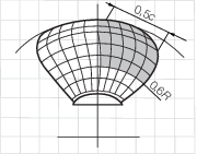
|
| Load case 5
|
60% of F
f or F
b
|
Uniform pressure applied on propeller face
(pressure side) to an area from 0,6R to the tip and from the trailing
edge to 0,2 times the chord length
|
|
11.13 Design loads on propulsion line – Blade failure load for
both open and nozzle propellers
11.13.1 The
force is acting at 0,8R in the weakest direction of the
blade and at a spindle arm of 2/3 of the distance of axis of blade
rotation of leading and trailing edge whichever is the greatest. The
blade failure load is to be taken as:
|
F
ex
|
= |

|
where
|
σ0,2 and σu
|
= |
representative values for the blade material |
|
c, t and r
|
= |
the actual chord length, thickness and radius of the cylindrical
root section of the blade at the weakest section outside root fillet
and typically will be at the termination of the fillet into the blade
profile. |
11.14 Design – Design principle
11.14.1 The
strength of the propulsion line is to be designed:
-
for maximum
loads in Pt 8, Ch 2, 11.7 Propeller ice interaction;
-
such that the
plastic bending of a propeller blade will not cause damage in other
propulsion line components;
-
with sufficient
fatigue strength.
11.15 Design – Azimuthing main propulsors
11.15.1 In
addition to the above requirements, special consideration will be
given to the loading cases which are extraordinary for propulsion
units when compared with conventional propellers. Estimation of the
loading cases must reflect the operational realities of the ship and
the thrusters. In this respect, for example, the loads caused by impacts
of ice blocks on the propeller hub of a pulling propeller are to be
considered. Also, loads due to thrusters operating in an oblique angle
to the flow are to be considered. The steering mechanism, the fitting
of the unit and the body of the thruster is to be designed to withstand
the loss of a blade without damage. The plastic bending of a blade
is to be considered in the propeller blade position, which causes
the maximum load on the studied component.
11.15.2 Azimuth
thrusters are also to be designed for estimated loads due to thruster
body/ice interaction as in Pt 8, Ch 2, 10.26 Appendages.
11.16 Blade design – Maximum blade stresses
11.16.1 Blade
stresses are to be calculated using the backward and forward loads
given in sub-Sections Pt 8, Ch 2, 11.9 Design ice loads for open propeller and Pt 8, Ch 2, 11.10 Design ice loads for ducted propellers. The stresses are to be calculated
with recognised and well documented FE-analysis or another acceptable
alternative method. The stresses on the blade are not to exceed the
allowable stresses, σall, for the blade material given
below. The calculated blade stress for the maximum ice load is to
comply with the following:
|
σcalc < σall
|
= |

|
where
|
σref
|
= |
reference
stress, defined as: |
|
|
= |
0,6 σ0,2 +
0,4σu whichever is less
|
|
σu and σ0,2
|
= |
representative values for the blade material. |
11.17 Blade design – Blade edge thickness
11.17.1 The
blade edge thicknesses, t
ed, and tip thickness t
tip, are to be greater than t
edge given
by the following formula:
where
|
x
|
= |
distance
from the blade edge measured along the cylindrical sections from the
edge and is to be 2,5 per cent of chord length, however not to be
taken greater than 45 mm. |
|
|
= |
In the tip area
(above 0,975R radius) x is to be taken as 2,5 per cent
of 0,975R section length and is to be measured perpendicularly
to the edge, however not to be taken greater than 45 mm.
|
|
|
= |
16 MPa for leading
edge and tip thickness |
11.17.2 The
requirement for edge thickness is to be applied for leading edge and
in case of reversible rotation open propellers also for the trailing
edge. Tip thickness refers to the maximum measured thickness in the
tip area above 0,975R radius. The edge thickness in the
area between the position of maximum tip thickness and edge thickness
at 0,975 radius has to be interpolated between edge and tip thickness
value and smoothly distributed.
11.18 Prime movers
11.18.1 The
main engine is to be capable of being started and running the propeller
with the CP in full pitch.
11.18.2 Provisions
are to be made for heating arrangements to ensure ready starting of
the cold emergency power units at an ambient temperature applicable
to the Polar class of the ship.
11.18.3 Emergency
power units are to be equipped with starting devices with a stored
energy capability of at least three consecutive starts at the design
temperature in Pt 8, Ch 2, 11.18 Prime movers 11.18.2.
The source of stored energy is to be protected to preclude critical
depletion by the automatic starting system, unless a second independent
means of starting is provided. A second source of energy is to be
provided for an additional three starts within 30 min., unless manual
starting can be demonstrated to be effective.
11.19 Machinery fastening loading accelerations
11.19.1 Essential
equipment and main propulsion machinery supports are to be suitable
for the accelerations as indicated in the following. Accelerations
are to be considered acting independently.
11.19.2 The
maximum longitudinal impact acceleration, al, at any point
along the hull girder is to be taken as:
|
a
l
|
= |
 m/s2 m/s2
|
where
|
H
|
= |
distance
from the waterline to the point being considered, in metres |
|
L
|
= |
length
between perpendiculars, in metres |
|
φ |
= |
maximum friction
angle between steel and ice, normally taken as 10, in degrees |
|
γ |
= |
bow stem
angle at waterline, in degrees |
11.19.3 The
combined vertical impact acceleration, a
v,
at any point along the hull girder, is to be taken as:
|
a
v
|
= |
 m/s2 m/s2
|
where
|
|
= |
1,3 at the AP for
vessels conducting icebreaking astern |
- intermediate values are to be determined by linear interpolation.
11.19.4 The
combined transverse impact acceleration, at, at any point
along hull girder, is to be taken as:
|
a
t
|
= |
 m/s2 m/s2
|
where
|
|
= |
1,5 at the AP for
vessels conducting icebreaking astern |
- intermediate values are to be determined by linear interpolation
11.20 Auxiliary systems
11.20.1 Machinery
is to be protected from the harmful effects of ingestion or accumulation
of ice or snow. Where continuous operation is necessary, means are
to be provided to purge the system of accumulated ice or snow.
11.20.2 Means
are to be provided to prevent damage due to freezing, to tanks containing
liquids.
11.20.3 Vent
pipes, intake and discharge pipes and associated systems are to be
designed to prevent blockage due to freezing or ice and snow accumulation.
11.21 Sea inlets and cooling water systems
11.21.1 Cooling
water systems for machinery that are essential for the propulsion
and safety of the vessel, including sea chest inlets, are to be designed
for the environmental conditions applicable to the ice class.
11.21.2 At
least two sea chests are to be arranged as ice boxes for classes PC1 to PC5 inclusive. The calculated volume for each
of the ice boxes is to be at least 1 m3 for every 750 kW
of the total installed power. For PC6 and PC7,
there is to be at least one ice box located preferably near centreline.
11.21.3 Ice
boxes are to be designed for an effective separation of ice and venting
of air.
11.21.4 Sea
inlet valves are to be secured directly to the ice boxes. The valves
are to be a full bore type.
11.21.5 Ice
boxes and sea bays are to have vent pipes and are to have shut off
valves connected directly to the shell.
11.21.6 Means
are to be provided to prevent freezing of sea bays, ice boxes, ship
side valves and fittings above the load waterline.
11.21.7 Efficient
means are to be provided to re-circulate cooling seawater to the ice
box. The total sectional area of the circulating pipes is not to be
less than the area of the cooling water discharge pipe.
11.21.8 Detachable
gratings or manholes are to be provided for ice boxes. Manholes are
to be located above the deepest load line. Access is to be provided
to the ice box from above.
11.21.9 Openings
in ship sides for ice boxes are to be fitted with gratings, or holes
or slots in shell plates. The net area through these openings is to
be not less than 5 times the area of the inlet pipe. The diameter
of holes and width of slot in shell plating is to be not less than
20 mm. Gratings of the ice boxes are to be provided with a means of
clearing. Clearing pipes are to be provided with screw-down type non-return
valves.
11.22 Ballast tanks
11.23 Ventilation system
11.23.1 The
air intakes for machinery and accommodation ventilation are to be
located on both sides of the ship.
11.23.2 Accommodation
and ventilation air intakes are to be provided with means of heating.
11.23.3 The
temperature of the inlet air provided to machinery from the air intakes
is to be suitable for the safe operation of the machinery.
11.24 Steering arrangements
11.24.1 The steering gear for ships assigned the notation Icebreaker
should be designed such that the rudder is centred automatically, immediately
before the ship goes astern.
11.24.2 The effective holding torque of the rudder actuator, at safety valve set
pressure, is obtained by multiplying the open water torque requirements
(QR) at open water design speed (maximum 18 knots) determined
from Pt 3, Ch 13, 2 Rudders, by the factor obtained from
Table 2.11.6 Steering gear holding torque factor.
Table 2.11.6 Steering gear holding torque factor
| Ice
Class
|
PC1
|
PC2
|
PC3
|
PC4
|
PC5
|
PC6
|
PC7
|
| Holding
torque factor
|
5
|
5
|
3
|
3
|
3
|
2
|
1,5
|
11.24.3 The rudder actuator is to be protected by torque relief arrangements,
assuming the turning speeds obtained from Table 2.11.7 Rudder turning speed for relief valve discharge capacity without undue pressure rise.
Table 2.11.7 Rudder turning speed for relief valve discharge capacity
| Ice
Class
|
PC1,
PC2
|
PC3, PC4,
PC5
|
PC6,
PC7
|
| Rudder
turning speed (degrees/second)
|
8
|
6
|
4
|
11.24.4 For icebreakers, additional fast acting torque relief arrangements
(acting at 15 per cent higher pressure than the set pressure of safety valves in
Pt 8, Ch 2, 11.24 Steering arrangements 11.24.2) are to provide effective protection of the rudder actuator in case
the rudder is pushed rapidly hard over against the stops assuming the turning speeds
obtained from Table 2.11.8 Rudder turning speed for fast acting relief valve discharge capacity. The arrangement is to be
such that steering capacity is readily regained. Fast acting torque relief
arrangements are recommended for ships without the Icebreaker notation.
Table 2.11.8 Rudder turning speed for fast acting relief valve discharge capacity
| Ice
Class
|
PC1,
PC2
|
PC3, PC4,
PC5
|
PC6,
PC7
|
| Rudder
turning speed (degrees/second)
|
40
|
20
|
10
|
11.25 Alternative design
11.25.1 As
an alternative a comprehensive design study may be submitted and may
be requested to be validated by an agreed test programme.
|