
Section
2 Minimum structural requirements
2.1 General
2.1.1 This
Section gives the basic principles to be adopted in determining the
Rule structural requirements.
2.1.2 The
equations given in this Section are to be used to determine the scantling
requirements for shell envelope, wet-deck, weather deck and inner
bottom, see
Vol 1, Pt 6, Ch 4, 4 Wet-deck.
2.2 Plate thickness
2.2.1 The
requirements for the thickness of plating, t
p,
is in general to be in accordance with the following:
2.3 Stiffener properties
2.3.1
Primary
stiffening members. The requirements for section modulus, inertia
and web area of primary stiffening members subjected to pressure loads
are, in general, to be in accordance with the following: Section Modulus:
Inertia:
Web area:
where
|
|
= |
f
σ is a structural element type
factor and is 0,5 in general, for primary stiffening members
|
|
|
= |
f
σ factors are listed for specific
structural items in Table 4.2.2 Stiffening type factors
|
|
|
= |
c
A, c
Z and c
l are coefficients defined in Table 4.2.1 Section modulus, inertia and web
area coefficients for different load models
|
|
|
= |
f
σ, f
τ, f
δ are defined in Table 4.2.3 Acceptance criteria
|
|
|
= |
P
des, S, l
e,
σyd, τyd and E are defined
in Vol 1, Pt 6, Ch 1, 1.3 Symbols and definitions 1.3.1.
|
2.3.2
Secondary
stiffening members. The requirements for section modulus, inertia
and web area of secondary stiffening members subjected to pressure
loads are, in general, to be in accordance with the following: Section
Modulus:
Inertia:
Web area:
where
|
|
= |
δf is a structural element type factor and is
0,8 in general, for secondary stiffening members
|
|
|
= |
δf factors are listed for specific structural
items in Table 4.2.2 Stiffening type factors
|
|
|
= |
c
A, c
Z and c
l are coefficients defined in Table 4.2.1 Section modulus, inertia and web
area coefficients for different load models
|
|
|
= |
f
σ, f
λ and f
δ are defined in Table 4.2.3 Acceptance criteria
|
|
|
= |
P
des, s, l
e ,σyd, τo and E are defined in Vol 1, Pt 6, Ch 1, 1.3 Symbols and definitions 1.3.1.
|
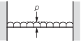
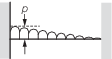
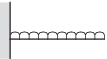
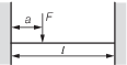
Table 4.2.1 Section modulus, inertia and web
area coefficients for different load models
| Load Model
|
Position (i)
|
|
Web area coefficient
C
A
|
Section modulus
coefficient C
Z
|
Inertia coefficient
C
I
|
Application
|
| 1 End
|
2 Midspan
|
3 End
|
(i)
|
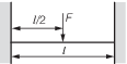
| (A)
|
|
1
|
1/2
|
1/2
|
—
|
Primary and other
members where the end fixity is considered encastre and the pressure is
uniformly distributed
|
| 2
|
—
|
–1/24
|
1/384
|
| 3
|
1/2
|
1/12
|
—
|
| (B)
|

|
1
|
1/2
|
1/10
|
—
|
Local, secondary and
other members where the end fixity is considered to be partial and the
pressure is uniformly distributed
|
| 2
|
—
|
–1/10
|
1/288
|
| 3
|
1/2
|
1/10
|
—
|
| (C)
|
|
1
|
7/20
|
1/20
|
—
|
Fully fixed and the
pressure is a linearly varying distribution
|
| 2
|
—
|
—
|
1/764
|
| 3
|
3/20
|
1/30
|
—
|
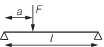
| (D)
|
|
1
|
1
|
1/2
|
1/8
|
Cantilever and uniformly
distributed pressure
|
| 2
|
—
|
—
|
—
|
| 3
|
—
|
—
|
—
|
| (E)
|

|
1
|
1/2
|
—
|
—
|
Simply supported and
uniformly distributed pressure
|
| 2
|
—
|
–1/10
|
5/384
|
| 3
|
1/2
|
—
|
—
|
| (F)
|
|
1
|
|
|
—
|
Fully fixed and a
single point load anywhere on the span
|
| 2
|
—
|
|
|
| 3
|
|
|
—
|
| (G)
|
|
1
|
1/2
|
1/8
|
—
|
Fully fixed and a single
point load at the centre of the span
|
| 2
|
—
|
–1/8
|
1/192
|
| 3
|
1/2
|
1/8
|
—
|
| (H)
|
|
1
|
|
—
|
—
|
Simply supported and a
single point load anywhere on the span
|
| 2
|
|
|
|
| 3
|
|
—
|
—
|
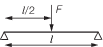
| (J)
|
|
1
|
1/2
|
—
|
—
|
Simply supported and a
single point load at the centre of the span
|
| 2
|
—
|
–1/4
|
1/48
|
| 3
|
1/2
|
—
|
—
|
Table 4.2.2 Stiffening type factors
| Structural element
|
δf
|
|
Shell envelope
|
|
|
|
Main hull bottom and
bilge longitudinals
|
|
|
|
Main hull
side longitudinals
|
|
|
|
Side hull
bottom and bilge longitudinals
|
0,8
|
|
|
Side hull side
longitudinals
|
|
|
|
Main hull bottom transverse
frames
|
|
|
|
Main hull
side frames
|
|
|
|
Side hull
bottom transverse frames
|
0,8
|
|
|
Side hull
side frames
|
|
|
|
Bottom
girders
|
|
|
|
Side
stringers
|
|
|
|
Floors
|
0,5
|
|
|
Bottom
transverse web frames
|
|
|
|
Side
transverse web frames
|
|
|
|
Wet deck
|
|
|
|
Wet-deck
longitudinals
|
0,8
|
|
|
Wet deck
transverse frames
|
|
|
Wet-deck
transverse web frames
|
0,5
|
|
|
Wet-deck
girders
|
|
|
Weather and exposed decks
|
|
|
|
Deck longitudinals
|
0,8
|
|
|
Deck beams
|
|
|
Deck girders
|
0,5
|
|
|
Deck transverses
|
|
|
Deck deep beams
|
|
|
Inner bottom
|
|
|
|
Inner bottom
longitudinals
|
0,8
|
|
|
Inner
bottom transverse frames
|
0,5
|
Table 4.2.3 Acceptance criteria
| Structural
item
|
Limiting criteria
|
| Longitudinally effective
structure
|
Bending stress
|
Stiffener web shear
stress
|
Stiffener deflection ratio
|
Buckling factor, Compressive stresses
See Note 3
|
| Stress descriptor
|
f
σ
|
f
τ
|
f
δ
|
λσ
|
| Plating
|
See Note 5
|
|
See Note 1
|
|
| Main hull bottom shell
|
f
2
|
—
|
0,00125
|
1,0
|
| Main hull side shell
|
f
2
|
—
|
0,00125
|
1,0
|
| Side hull bottom shell
|
0,9f
2
|
—
|
0,00125
|
1,0
|
| Side hull side shell
|
0,9f
2
|
—
|
0,00125
|
1,0
|
| Wet-deck
|
0,9f
2
|
—
|
0,00125
|
1,0
|
| Weather
deck, outboard the line of openings
|
f
2
|
—
|
0,00100
|
1,0
|
| Inner
bottom
|
1,4f
2
|
—
|
0,00125
|
1,0
|
| Secondary stiffeners
|
|
|
See Note 1
|
1,1
|
| Main hull
bottom and bilge longitudinals
|
f
2
|
0,65
|
0,00125
|
1,1
|
| Main hull
side longitudinals
|
f
2
|
0,65
|
0,00125
|
1,1
|
| Side hull
bottom and bilge longitudinals
|
f
2
|
0,65
|
0,00125
|
1,1
|
| Side hull
side longitudinals
|
f
2
|
0,65
|
0,00125
|
1,1
|
| Wet-deck
longitudinals
|
f
2
|
0,65
|
0,00125
|
1,1
|
| Main hull
bottom transverse frames
|
0,65
|
0,65
|
0,00125
|
1,1
|
| Main hull
side frames
|
0,65
|
0,65
|
0,00125
|
1,1
|
| Side hull
bottom transverse frames
|
0,65
|
0,65
|
0,00125
|
1,1
|
| Side hull
side frames
|
0,65
|
0,65
|
0,00125
|
1,1
|
| Wet-deck
transverse frames
|
0,65
|
0,65
|
0,00125
|
1,1
|
| Weather
deck longitudinals
|
f
2
|
0,65
|
0,00100
|
1,1
|
| Weather deck
beams
|
0,65
|
0,65
|
0,00100
|
1,1
|
| Inner bottom
longitudinals
|
f
2
|
0,65
|
0,00125
|
1,1
|
| Primary
stiffeners
|
|
|
See Note 2
|
|
| Single
bottom girders
|
0,75
|
0,65
|
0,00100
|
1,0
|
| Double
bottom girders
|
0,75
|
0,80
|
0,00100
|
1,0
|
| Side
stringers
|
0,75
|
0,65
|
0,00100
|
1,0
|
| Floors
|
0,75
|
0,65
|
0,00100
|
1,0
|
| Bottom
transverse web frames
|
0,65
|
0,65
|
0,00100
|
1,0
|
| Side
transverse web frames
|
0,65
|
0,65
|
0,00100
|
1,0
|
| Wet-deck
transverse web frames
|
0,65
|
0,65
|
0,00100
|
1,0
|
| Wet-deck
girders
|
0,75
|
0,65
|
0,00100
|
1,0
|
| Deck
transverses
|
0,75
|
0,65
|
0,00100
|
1,0
|
| Deck deep
beams
|
0,65
|
0,65
|
0,00100
|
1,0
|
| Wet-deck
transverse frames
|
0,65
|
0,65
|
0,00100
|
1,0
|
| Weather
deck girders
|
0,75
|
0,65
|
0,00100
|
1,0
|
| Weather
deck transverses
|
0,65
|
0,65
|
0,00100
|
1,0
|
| Weather deck
deep beams
|
0,65
|
0,65
|
0,00100
|
1,0
|
| Symbols
|
|
f
2 is applicable to stiffeners and plating subjected to global
hull girder bending stresses and local bending stresses and is to be taken
as follows:
but not greater than 0,95. Note that for initial design
assessment f
2 may be taken as 0,75.
|
| where
|
| σhg is the stress due to hull girder
bending in the appropriate structural item, see
Vol 1, Pt 6, Ch 3, 2.4 Longitudinal bending strength 2.4.4
|
| σa is the lower of
|
|
|
| λσ is the buckling factor for this item
|
| σcr is the critical buckling stress,
see Note 4.
|
Note
1. Deflection ratio for secondary
stiffeners, expressed as a ratio of the stiffener's span, i.e. δ ≤
f
δ x span where ∊ is the deflection
Note
2. Deflection ratio for secondary
stiffeners, expressed as a ratio of the stiffener's span, i.e. δ ≤
f
δ x span where ∊ is the deflection
Note
3. Buckling factor of safety to be
applied to the compressive stress due to global longitudinal
stresses
Note
4. If the Complementary Rules are the
Rules and Regulations for the Classification of Naval Ships
(hereinafter referred to as the Rules for Naval Ships) then see
Vol 1, Pt 6, Ch 2, 4 Vibration control of the Rules for
Naval Ships. If the Complementary Rules are the Rules and
Regulations for the Classification of Ships (hereinafter
referred to as the Rules for Ships) then see
Pt 3, Ch 4, 7 Hull buckling strength of the Rules for Ships. If
the Complementary Rules are the Rules and Regulations for the
Classification of Special Service Craft (hereinafter referred
to as the Rules for Special Service Craft) then see
Pt 6, Ch 7, 4 Buckling control of the Rules for Special
Service Craft.
Note
5. If the Complementary Rules are the
Rules for Special Service Craft then for bottom, bow and
wet-deck slamming f
2 is to be taken as 0,85.
|
|