
Section
5 Hydraulic cylinders
5.1 General
5.1.2 For the purposes of certification or classification of lifting
appliances, hydraulic cylinders will be considered for structural adequacy including
the effects of hydraulic pressure. Although they are not considered to be pressure
vessels, they will nevertheless be required to undergo a pressure load test at the
manufacturer’s works. See
Ch 9, 5.9 Testing for testing requirements.
5.1.3 Hydraulic cylinders with special features, such as telescopic types
(including versions with intermediate supports), self-locking types, with trunnion
mounts, with unconventional or no eye plates at one or both ends, etc. shall, as far
as possible, be designed in accordance with the requirements outlined in this
Section. In such cases, design calculations covering those special features will be
required to be submitted.
5.1.4 Where hydraulic cylinders are used in applications covered by specialist
Chapters in this Code, requirements given in those Chapters relating to hydraulic
cylinders shall also be taken into consideration as applicable.
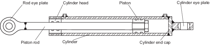
Figure 9.5.1 Hydraulic cylinder
(simplified)
5.2 Definitions
5.2.1 Design pressure
The design pressure, PD is the maximum internal pressure for which
the cylinder has been designed. The design pressure is not to be less than the
highest set pressure of any relief valves in the hydraulic system and/or relief
valves mounted directly on the hydraulic cylinder ports.
5.2.2 Working pressure
The maximum working pressure, Pw, is the maximum
dynamic internal pressure that the cylinder may be subject to in operation which
includes internal pressures generated by external forces e.g. due to the SWL
enhanced by the hoisting factor, accelerations etc., but excludes short duration
pressure peaks (See
Ch 9, 5.3 General design requirements 5.3.6). The
maximum working pressure is not to exceed the design pressure, PD.
5.2.3 Relief valve pressure setting
The relief valve setting is the pressure at which the relief valve is set to
activate.
5.3 General design requirements
5.3.1 Welded cylinder pipes should not generally be used for hydraulic cylinder
applications. Proposals to use welded cylinder pipes will be specially considered
and need to be agreed with LR. The weld procedure including any heat treatment and
non-destructive examination shall be submitted to LR for appraisal.
5.3.2 The cylinder head (or gland) shall have adequate length and capability to guide the
piston rod under load including the self-weight of the hydraulic cylinder. The seals
are to be adequate to prevent hydraulic leakage, and water and dirt entering the
cylinder.
5.3.3 The piston rod shall be suitably finished and coated to ensure adequate sealing
capability and corrosion protection.
5.3.4 The eye plates shall be equipped, where possible, with spherical bearings to prevent
additional end bending moments being introduced. The design shall not allow free
movement of the eye plate between the supporting plates in the direction of the pin.
Alternative arrangements will be specially considered.
5.3.5 The relief valve pressure setting shall not exceed the design pressure.
This setting may be temporarily increased to allow the crane to be proof load
tested, but is to be reset for normal operations. See
Ch 9, 5.9 Testing 5.9.5. To prevent unnecessary
activation of the relief valve, it is desirable that there should be a margin
between the normal pressure at which the hydraulic cylinder operates and the lowest
pressure at which any relief valve is set to lift. The relief valve setting may be
up to 1,25 times the maximum working pressure. Alternative proposals will be
specially considered.
5.3.6 Short duration pressure peaks which exceed the maximum working pressure,
Pw, typical of certain offshore crane applications, need not
be considered in determination of the maximum working pressure providing the
pressure peaks are less than 0,94 x Hydraulic Test Pressure, PT
(see
Ch 9, 5.9 Testing 5.9.1) and less than
or equal to the Design Pressure, PD.
5.4 Design criteria
5.4.1 Hydraulic cylinders fitted to lifting appliances are to be designed to
withstand the load combinations as given in the Chapter relevant to the actual
application (see
Ch 4, 2.15 Load combinations and Ch 4, 3.5 Load combinations for Shipboard and
Offshore cranes, Ch 7, 2.5 Load combinations for Lifts). The factored
forces (hoisting and duty factor, as applicable), stowage, test load and any
exceptional conditions resulting from the actual application shall be
considered.
5.4.2 Hydraulic cylinders fitted to life-saving appliances are to be designed to meet the
operational and load test conditions required by SOLAS and the IMO LSA Code as
applicable.
5.4.3 Depending on the design of the hydraulic cylinder the following calculations and
validations are usually required to be carried out as a minimum:
- The eye plates shall be designed for the following conditions,
see
Ch 9, 5.8 Proof of strength and stability 5.8.4:
- local bending, normal and shear-out stress due to pull
forces.
- bearing stress due to pull and push forces.
- The following threaded, bolted and/or welded connections (as
applicable) are to be calculated as per Ch 9, 5.8 Proof of strength and stability 5.8.1,
Ch 4, 2.23 Allowable stress – Joints and connections (as
applicable) and/or Ch 9, 5.8 Proof of strength and stability 5.8.2
respectively:
- connection of cylinder or rod eye plates with the
cylinder’s end cap or piston rod.
- connection of piston with piston rod.
- connection of cylinder head with cylinder tube.
- connection of cylinder end cap with cylinder tube.
- The thickness of the end cap can be calculated as detailed in Ch 9, 5.8 Proof of strength and stability 5.8.2.
- The hoop and longitudinal stress of the hydraulic cylinder wall
shall be calculated as detailed in Ch 9, 5.8 Proof of strength and stability 5.8.5.
- Diametrical expansion of cylinders with large bores possibly affecting the
sealing of the piston is to be considered.
- Bolted connections are to be designed in compliance with Ch 4, 2.23 Allowable stress – Joints and connections. Tapped
holes are to be in compliance with Ch 9, 5.8 Proof of strength and stability 5.8.1.
The thread-engaging length is to be at least 1,5 times the major bolt diameter.
- Axial forces on piston rod.
- External pressure on hollow piston rods shall be taken into consideration as
applicable.
- The pins supporting the eye plates shall be calculated for shear and bending
stresses.
- Trunnion mounts (if fitted) to the cylinder tube.
- Additional calculations for other components of the hydraulic cylinder may be
required depending on the actual design.
5.4.4 For the evaluation of the required design, working and relief valves pressures, it is
not required to take the duty factor into account. For all other design
calculations, the duty factor is required to be taken into consideration.
5.5 Materials
5.5.1 The material requirements (including the Charpy V-notch test
requirements) are to be as per the Chapters applicable to the appliance the
hydraulic cylinder will be used in. For lifting appliances the materials for
hydraulic cylinders are to be selected to meet the requirements detailed in Ch 11 Materials and Fabrication and Ch 4, 2.25 Materials. For life-saving appliances the
materials for hydraulic cylinders are to be selected to meet the requirements of
Ch 11 Materials and Fabrication and Ch 3, 1.11 Materials.
5.5.2 The materials used for hydraulic cylinder applications are to be sufficiently
ductile. Materials that have an elongation of less than 14 per cent shall be
specially considered by LR.
5.5.3 Pressure retaining parts of carbon-manganese steel grades are to be delivered in the
normalised or hot finished condition, whereas alloy grade steels are to be delivered
in the quenched and tempered condition.
5.5.4 The use of stainless steel products in hydraulic cylinder applications is required to
be specially considered by LR.
5.5.5 In cases where hydraulic cylinders are fitted to life-saving appliances, attention is
drawn to materials where the yield strength is very low compared to the ultimate
tensile strength. In such cases, it is particularly important to consider the proof
load test case as a design case in order to prevent actual stresses being in excess
of the yield strength of the material.
5.5.6 For hydraulic cylinder components subjected to tensile loads (e.g. cylinder end caps
on pull cylinders) consideration is to be given to the application of Z-grade
material. For the evaluation whether Z-grade materials are to be used in the design
the methods and criteria of a recognised National or International Standard can be
applied.
5.6 Safety features
5.6.1 Hydraulic cylinders are to be equipped with pilot-operated non-return
valves at both the inlet and outlet manifolds to ensure that the cylinders remain in
position in the event of a hydraulic failure (e.g. hose/tube rupture). The required
pilot-operated non-return valves are to be fitted directly to the cylinder ports.
The cylinder ports shall either be an integral part of the cylinder wall or shall be
connected by means of full penetration welds. Proposals to use valve types other
than pilot-operated non-return valves will be specially considered.
5.6.2 The hydraulic system shall be equipped with relief valves to protect the
system against overpressure in the hydraulic circuit originating from the lifting
appliance itself or the hydraulic system/pump.
5.7 Allowable stresses
5.7.2 For hydraulic cylinders subject to push loading a second order buckling analysis is
to be carried out unless it can be demonstrated that a simplified analysis would
give conservative results.
5.7.4 In second order buckling calculations, the hydraulic cylinder shall be idealised
taking into account the relevant cross-sections (piston rod and cylinder) and shall
be calculated by means of the principles of the 2nd order theory. The calculation
shall include all relevant, but at least, the following influences:
- Dead weight and angle of the hydraulic cylinder;
- at least a sinusoidal pre-deformation of L/300 along the various possible
hydraulic cylinder lengths (other types and values of pre-deformations maybe
required and will be specially considered);
- any hoisting factor and material stress factor to be used to enhance the
external load used in the calculation;
- the bending stresses (due to 2nd order theory) of the cylinder
shall be superimposed with the hoop and radial stress due to internal
pressure (reference is made to Ch 9, 5.8 Proof of strength and stability 5.8.5);
- as this is a 2nd order analysis, all safety (stress factor, hoisting factor,
etc.) need to be placed on the load side.
5.7.5 Alternative proposals to demonstrate adequate safety against column buckling will be
specially considered.
5.8 Proof of strength and stability
5.8.1 Threaded connections (as opposed to bolted connections) shall be calculated as
follows:
where
|
τTh |
= |
shear stress in thread, in MPa |
|
F |
= |
axial force applied to the threaded connection, in N |
|
d3 |
= |
root diameter of the threaded connection, in mm |
|
l |
= |
length of the threaded connection, in mm |
|
τa |
= |
allowable shear stress, in MPa |
The hydraulic cylinder tube thickness at the threaded section is to be
not less than the required thickness for internal pressure measured at the bottom of
the internal thread. Alternatively, detailed calculations for the threaded
connection as per a recognised National or International Standard (e.g. EN 14359)
may be performed and submitted for consideration.
5.8.3 The hydraulic cylinder end cap may be calculated using the formula below:
where
|
σec |
= |
bending stress in the end cap due to internal pressure, in MPa |
|
p |
= |
internal pressure acting on the end cap, in MPa |
|
do |
= |
outer diameter of the cylinder, in mm |
|
di |
= |
inner diameter of the cylinder, in mm |
|
υ |
= |
Poisson's ratio |
|
t |
= |
wall thickness of the end cap, in mm |
|
σa |
= |
allowable bending stress as per Ch 9, 5.7 Allowable stresses , in MPa |
The above method outlines a simplified approach which does not take into account
possible reinforcements of eye plate connected to the end cap. If the end cap is
reinforced and the above stress proof fails, alternative means of analysis may be
applied.
5.8.4 The eye plates of the hydraulic cylinders may be calculated using the methods of a
recognised National or International Standard.
5.8.5 The hoop, longitudinal and radial stresses in the hydraulic cylinder wall can be
calculated using the formulae below:
- Hoop stress, in MPa
where
|
σH |
= |
cylinder hoop stress, in MPa |
|
p |
= |
internal pressure, in MPa |
|
do |
= |
external cylinder diameter, in mm |
|
di |
= |
internal cylinder diameter, in mm |
|
x |
= |
actual diameter of the hydraulic cylinder wall stresses
are required to be evaluated, in mm |
|
σa |
= |
allowable stress as per Ch 9, 5.7 Allowable stresses ,
in MPa |
- Longitudinal (axial) stress, in MPa
where
|
σL |
= |
cylinder longitudinal (axial) stress, in MPa |
- Radial stress, in MPa
where
|
σR |
= |
Radial stress, in MPa |
5.8.6 Equivalent stress
The equivalent stress shall be calculated taking into account the following
stresses:
- Cylinder tube:
- Hoop stress (due to internal pressure).
- Radial stress (due to internal pressure).
- Axial stress (due to external force and/or internal pressure).
- Bending stress (due to 2nd order bending, see
Ch 9, 5.7 Allowable stresses 5.7.4).
- Piston rod:
- Hoop stress (due to external pressure in case of a hollow piston).
- Radial stress (due to external pressure in case of a hollow
piston).
- Axial stress (due to external force).
- Bending stress (due to 2nd order bending, see
Ch 9, 5.7 Allowable stresses 5.7.4).
5.8.7 Where appropriate, fatigue calculations are to be carried out in accordance with a
recognised National or International Standard using load cycles and a load spectrum
agreed between the manufacturer and the Owner.
5.8.9 Cases where the piston is in contact with the end cap or the cylinder head shall be
taken into consideration for the design of the hydraulic cylinder. This is of
particular importance for cases where the push or pull forces for the contact
situation are above those which can be generated by design internal pressures.
5.9 Testing
5.9.1 The hydraulic cylinder is to be hydraulically tested with the maximum of
the following defined test pressures pT:
- pT = 1,5 pW
- pT = 1,3 pD
where
|
pT |
= |
hydraulic test pressure, in MPa |
|
pW |
= |
maximum working pressure, in MPa |
|
pD |
= |
maximum design pressure, MPa |
5.9.2 The minimum hydraulic test pressure for life-saving appliances shall be the pressure
in the hydraulic cylinder required for the prototype test of 2,2 times the SWL
amplified by an additional safety factor of 1,06. Hydraulic test pressures for
life-saving appliances used in offshore applications are often dependant on national
administrations’ requirements and will be specially considered.
5.9.3 The hydraulic cylinders are also to be tested as part of the proof load testing of
the lifting or life-saving appliances.
5.9.4 The designer shall ensure that the hydraulic cylinder design is able to
withstand the hydraulic test pressure as defined in Ch 9, 5.9 Testing 5.9.1 and the proof load testing of the
lifting or life-saving appliance. The proof loads for lifting appliances are defined
in Ch 12, 1.5 Derricks and derrick cranes.
The proof loads for life-saving appliances are defined in Ch 3, 1.12 Testing. The actual
stresses due to the applied test pressure and due to proof load testing of the
hydraulic cylinders shall not exceed the allowable stresses stated in the relevant
chapters applicable to the appliance being considered (see
Ch 4, 2.17 Allowable stress – Elastic failure for the test
loadcase (case 4) for both lifting and life-saving appliances, Ch 6, 5.2 Load combinations for
Ro-Ro access equipment, etc.).
5.9.5 After proof load testing of the lifting or life-saving appliance, the pressure relief
valve is to be reset by the manufacturer to the appropriate operational setting to
ensure the appliance cannot be overloaded.
5.10 Handling of personnel
5.10.1 Luffing, folding and telescoping motion shall be realised by two independent
hydraulic cylinders where each cylinder is able to hold the SWL for handling of
personnel. Alternative arrangements using one hydraulic cylinder will be specially
considered.
|